NIRCam Multistripe Subarrays for Grism Time Series Spectroscopy
The JWST NIRCam detector multistripe subarrays expand the normal subarray capabilities by allowing multiple substripes (rows of pixels) to be read out, sampling different locations on the detector, or re-sampling a single substripe multiple times, within the subarray frame time. The ability to split subarrays into multiple substripes was introduced for Cycle 4, and is available for the NIRCam short wavelength grism time series capability.
On this page
See also: APT NIRCam Grism Time Series template, JWST Multistripe, Superstripe, and Substripe Detector Modes, NIRCam Superstripe Subarrays for Imaging and Time Series Imaging
Overview of multistripe subarray operations for H2RG detectors
Words in bold are GUI menus/
panels or data software packages;
bold italics are buttons in GUI
tools or package parameters.
Multistripe configuration parameters
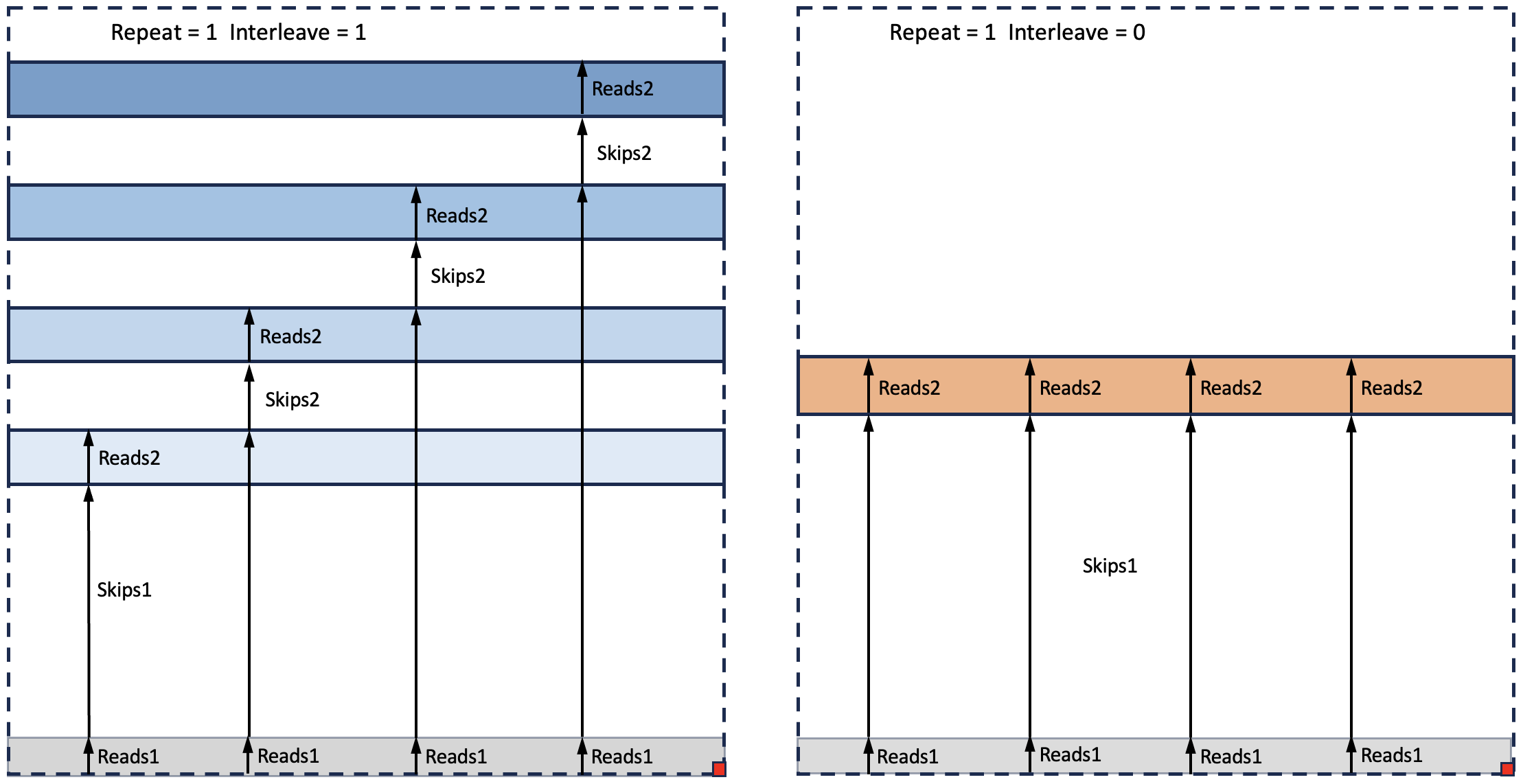
There are 6 primary parameters controlling the size, number and placement of substripes for a given subarray, as illustrated in Figure 1. All of the substripe parameters are pre-determined and presented in APT as a single subarray choice. The detail provided here is intended to provide a basic understanding of how multistripe exposures operate "under the hood": observers will not see them in APT or elsewhere in the planning tools.
Figure 1. Schematic showing multistripe subarrays and associated configuration parameters
Click on the figure for a larger view.
Notional placement and sizes of substripes in the multistripe subarrays used for DHS Time Series exposures. The left panel show the implementation for the short wavelength channel detectors (Repeat = 1, Interleave = 1), while the long wavelength channel setup is at right (Repeat = 1, Interleave = 0). The dashed lines represent the extent of a single detector, red squares are the origin of the subarray commanding coordinate system, and the extent of the substripes is shown by the shaded rectangles. Reads1 is used to read bottom row(s) of reference pixels immediately prior to reading Reads2 rows in each substripe. In NIRCam's short wavelength channel Skips1, Reads2 and Skips2 values are optimized to read out 1, 2 or 4 spectra from the NIRCam DHS grisms on a given detector. In NIRCam's long wavelength channel the same set of Reads2 rows of pixels gets read out multiple times during a subarray frame time.
- Reads1: Number of rows of pixels to read in the 1st substripe.
- The position of the first row is controlled by the RowCorner of the subarray (configured prior to the start of a multistripe exposure).
- The subarray RowCorner is set to 1, so that Reads1 rows of reference pixels are read out at the start of each substripe.
- Skips1: Number of rows of pixels to skip after reading "Reads1" rows of pixels.
- Reads2: Number of rows of pixels to read in the 2nd and subsequent substripes.
Note: The subarray frame size is set to exactly the size needed to hold the desired number of substripes and corresponding reference pixels. - Skips2: Number of rows of pixels to skip between the first and subsequent sets of "Reads2" rows.
The 5th and 6th parameters, Repeat and Interleave, control whether and how rows of reference pixels are included within a given read of the subarray frame. Figure 2 illustrates how the pixel data from the NIRCam substripe exposures are stored in the SW and LW channel subarray frames.
Figure 2. Organization of substripe pixel data within subarray frames for grism time-series exposures using the DHS in the SW channel

Click on the figure for a larger view.
The subarray frame size is the same for NIRCam's SW and LW channels, as are the number of reference rows (Reads1) and the number of rows in each substripe (Reads2). In the SW-channel subarray frames, pixel data from substripes with different locations (indicated by different shades of blue in the left panel) are interleaved with reads of reference pixel rows; in the LW-channel, repeated reads of a single substripe are interleaved with reads of the reference rows. Color scheme is the same as in Figure 1. See Figures 4 and 5 below for example subarray images.
For NIRCam, a single subarray frame size is used on all detectors for a given observation, and in both the short and long wavelength channels. That subarray size determines the total number of rows and columns within the subarray and the resulting frame time. Multistripe subarrays obey this same logic, with the same number of rows, columns and frame time on all detectors, but the values of the 6 parameters above are individually configurable for each detector within those constraints. The flexibility to individually set the 6 parameters is used, for example, to sample multiple spectra from the target in the short wavelength channel (Figure 1 left panel) while repeatedly sampling the single spectrum from the target in the long wavelength channel (Figure 1 right panel). The cadence of sampling in the long wavelength channel is higher than in the short wavelength channel by a factor of the number of individual substripes in the short wavelength channel. Skipping over rows occurs during existing overheads, so the frame time for a multistripe subarray is the same as for a normal subarray of the same size.
Multistripe timing equations
The substripes of a multistripe subarray frame are read out within the normal frame time for that subarray: no additional overheads are incurred while stepping over the Skips1 or Skips2 rows of pixels. The NIRCam Grism Time Series multistripe subarrays are all read out through 4 outputs and are 2048 columns wide, and the overall subarray frame time for them is computed as usual:
tframe = ((Ncolumns / Noutputs + 12) × (Nrows + 1) + 1) × 10.00 µsec ,
The two +1 terms above represent overheads that occur once at the end of a completed subarray frame.
Because the two +1 terms occur only once per subarray frame, the time to read a substripe is shorter than the time to read a subarray of the same size:
tstripe = (Ncolumns / Noutputs + 12) × Reads# × 10.00 µsec, where Reads# is either "Reads1" or "Reads2".
To obtain the total frame time in terms of the individual stripe times, the frame overhead needs to be added back:
tframe = tstripe(Reads1) + tstripe(Reads2) + ((Ncolumns / Noutputs + 12) × 1 + 1) × 10.00 µsec,
which is equivalent to the first equation with Nrows = Nstripe × (Reads1 + Reads2) because Ncolumns and Noutputs are the same for all substripes in the subarray.
Figure 3 is a comparison of the timing of reads within a subarray frame on a SW-channel detector and a LW-channel detector during a grism time-series integration. Both channels have the same total frame time, but the Reads2 substripe in the long wavelength channel is read out once for each substripe in the short wavelength channel.
Figure 3. Timing of reads within NIRCam DHS substripe subarray frames for the SW and LW channels

Click on the figure for a larger view.
Schematic showing the timing of substripe reads for 2 subarrays with the same value of Reads2, one consisting of 5 distinct substripes (SW channel, left), and the other with 5 repeating substripes (LW channel, right). In the example on the right, the single substripe is sampled 5 times more frequently than the left example. The solid red lines show the resets at the beginning and end of the integration. On the left, the triangles represent the readout of the first pixel of each substripe. The blue-red-blue color sequence of the triangle symbols represents the frames (or groups) within an integration (7 total in this case); the same color scheme is used in the right hand panel and shows the read time of the first pixel of the single substripe: that substripe is read out 5 times per frame time while each substripe on the left is read out once per frame time. Note that readout of the Reads1 rows of pixels is not included in the figure: in both panels Reads1 rows would be read out prior to the first substripe sample.
Figure 4. Laboratory images illustrating a NIRCam SW channel substripe exposure

Click on the figure for a larger view.
Left: Laboratory full frame image with illumination through a focal plane mask with 10 slits representing the 10 spectra produced by the NIRCam DHS grism element. Right: Individual subarray frames from a multistripe integration with the same illumination as in the left-hand panel. Black rectangles on the left show the 10 substripes used in the multistripe exposure for the SW channel substripe definition; images on the right show how reads of the substripes are collected into a single subarray frame with intervening rows of pixels removed. On the right, DN increases for all substripes for each frame during the integration.
Figure 5. Laboratory images illustrating a NIRCam LW channel substripe exposure

Click on the figure for a larger view.
Left: Laboratory full frame image with illumination through a focal plane mask with 10 slits; the image from a single slit is used to represent the single spectrum from the long wavelength grism. Right: Individual subarray frames from a substripe integration with the same illumination as in the left-hand panel. The black rectangle on the left shows the single substripe used in the LW channel integration; images on the right show how multiple reads of the same substripe are collected into a single subarray frame. On the right, DN increases for each repeated substripe within a subarray frame as well as for subsequent frames during the integration.