MIRI Detector Overview
MIRI uses 3 arsenic-doped silicon impurity band conduction (Si:As IBC) detectors, one in the imaging module, and 2 in the medium-resolution spectrometer (MRS).
On this page
MIRI has 3 nearly identical detectors. One is used in the imager. The other 2 are in the medium-resolution spectrometer (MRS), one for the short-wavelength channel and the other for the long-wavelength channel.
The MIRI photodetectors are composed of semiconductor material that creates free charge carriers (i.e., electrons) when photons are absorbed. These arsenic-doped silicon impurity band conduction (Si:As IBC) devices are sensitive to electromagnetic radiation from 5 to 28.5 μm (Rieke et al. 2015).
For science observations, observers must consider:
- detector performance, which includes basic detector characteristics such as gain, read noise, quantum efficiency, and dark current;
- readout patterns that determine the total integration time; and
- subarrays that allow for smaller regions of interest (ROI) to be read out at faster speeds to allow for brighter targets and specific observing modes.
Table 1. MIRI Si:As IBC detector properties
| Property | Value |
|---|---|
| Components | Si:As IBC devices manufactured by Raytheon Vision Systems (RVS) |
| Wavelength range | 5 to 28 µm |
Pixel format | 1024 × 1024 |
Pixel size | 25 µm |
Plate scale | 0.11"/pixel |
Nominal operating temperature | ≤6.7 K |
Dark current | <0.2 e–/s/pix (median) |
Read noise | ~14 e– (CDS) |
Full well | ~250,000 e– |
Conversion gain | 5.5 e–/DN |
Impurity band conduction (IBC) devices
The MIRI Si:As IBC differ from the shorter wavelength HgCdTe near-IR photodiodes, which would have too high a dark current if tuned for longer wavelengths. (Rieke et al. 2007)
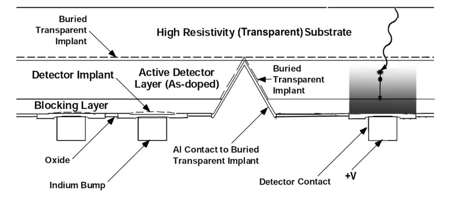
The IBC detectors have a long heritage, as similar devices were used in all 3 Spitzer instruments (IRAC [Hora et al. 2008]; IRS [Van Cleve et al. 1995], [Houck et al. 2004]; MIPS [Gordon et al. 2005]), in WISE (Mainzer et al. 2008), in MSX (Mill et al. 1994), and in Akari (Onaka et al. 2007). These detectors benefit from high quantum efficiencies (QE), low dark current, and resistance to the effects of cosmic radiation. A schematic of the IBC detector technology is shown in Figure 2. The design is referred to as either a blocked impurity band (BIB) or impurity band conductor (IBC device), depending on the vendor.
The MIRI Si:As IBC detectors are manufactured on a transparent substrate (top layer) that is lightly doped (high resistivity). Doping is a process that intentionally introduces impurities into a semiconductor to obtain the desired electrical properties. The next layer is 25–35 μm thick, arsenic doped, and absorbs the photons. An electric field (shaded grey) is set up across this layer using both the detector contact and the buried transparent implant. The purpose of the electric field is to draw the freed charge carriers towards the readout electronics. The next layer (bottom layer) is set up to both block thermal generated free charge carriers in the arsenic impurity level and allow photoelectrons to pass towards the readout electronics. This array is ultimately hybridized to a readout wafer by making contact to an output amplifier through the individual bump bonds of indium metal for each pixel.
References
Glasse, A. et al. 2015, PASP, 127, 686
The Mid-Infrared Instrument for the James Webb Space Telescope, IX: Predicted Sensitivity
Gordon et al. 2005, PASP, 117, 503
Reduction Algorithms for the Multiband Imaging Photometer for Spitzer
Hora, J. L. et al. 2008, PASP, 120, 1233
Photometry using the Infrared Array Camera on the Spitzer Space Telescope
Houck, J. R. et al. 2004, Proc. of SPIE, 5487, 62
The infrared spectrograph on the Spitzer Space Telescope
Mainzer, A. et al. 2008, Proc. of SPIE, 7021, 70210X-1
Characterization of flight detector arrays for the wide-field infrared survey explorer
Mill, J. D. et al. 1994, JSpRo, 31, 900
Midcourse space experiment: Introduction to the spacecraft, instruments, and scientific objectives
Onaka, T. et al. 2007, PASJ, 59, 401
The Infrared Camera (IRC) for AKARI -- Design and Imaging Performance
Ressler, M. E. et al. 2015, PASP, 127, 675
The Mid-Infrared Instrument for the James Webb Space Telescope, VIII: The MIRI Focal Plane System
Rieke, G. H. et al. 2004, ApJS, 154, 25
The Multiband Imaging Photometer for Spitzer (MIPS)
Rieke, G.H. 2007, ARA&A, 45, 77
Infrared Detector Arrays for Astronomy
Rieke, G. H. et al. 2015, PASP, 127, 665
The Mid-Infrared Instrument for the James Webb Space Telescope, VII: The MIRI Detectors
Van Cleve, J. E. et al. 1995, Proc. of SPIE, 2553, 502
Evaluation of Si:As and Si:Sb blocked-impurity-band detectors for SIRTF and WIRE
