MIRI Imaging Known Issues
Known issues specific to MIRI imaging data processing in the JWST Science Calibration Pipeline are described in this article. This is not intended as a how-to guide or as full documentation of individual pipeline steps, but rather to give a scientist-level overview of issues that users should be aware of for their science.
On this page
Specific artifacts are described in the Artifacts section below. Guidance on using the pipeline data products is provided in the Pipeline Notes section along with a summary of some common issues and workarounds in the summary section.
Please also refer to MIRI Imaging Calibration Status for an overview of the current astrometric and flux calibration of MIRI imaging data products.
Artifacts
Imager "scar"
The imager scar consists of a diagonal feature on the top-left part of the MIRI imager, centered at pixel (428,987) with a length of 16 pixels. This is related to a scratch on the surface of the detector. Although the pixels are responsive, this feature can scatter the light in both directions perpendicular to the scratch.
When the pixels associated with the scar are uniformly illuminated (no sources and just background), 2 diagonal features can run parallel to the scar (Figure 1). These stripes are brighter than the local background and their position and width change as a function of wavelength.
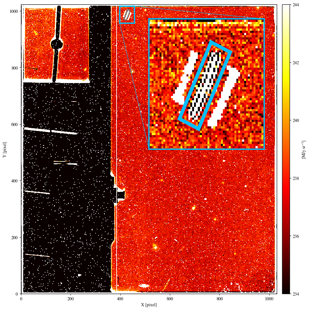
Click on the figure for a larger view.
MIRI F2100W image of PID 1040. The imager scar (highlighted by a light-blue rectangle in the zoomed-in panel) is located in the top-left part of the MIRI imager. The 2 diagonal features that run parallel to the scar are caused by light scattered in both directions perpendicular to the scratch, and are present when the scar is uniformly illuminated (no sources and just background).
If a bright source is imaged on these pixels, its light is scattered on the detector perpendicular to the scar creating a peculiar structure different from the classical point-like profile the same source would have in a different part of the imager (Figure 2).

Click on the figure for a larger view.
Example of a point source imaged on top of the MIRI imager scar. In these 2 MIRI F560W images of PID 1518, the profile of the same bright star changes significantly when the star is imaged on pixels far from (left panel) or associated with (right panel) the scar. As in Figure 1, the light blue rectangle in the right panel marks the location of the scar.
Imager bad pixels
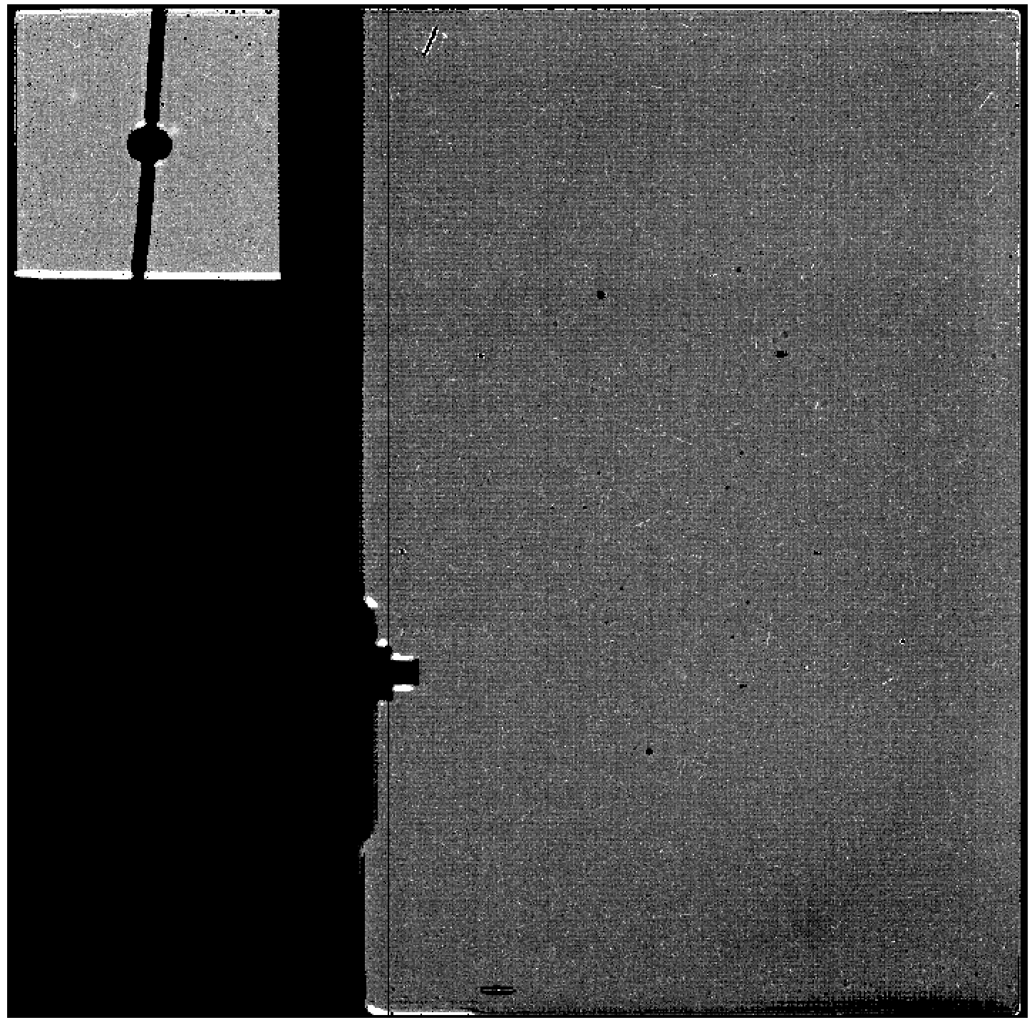
The MIRI imager detector has several pixels that are flagged based on ground testing and in-orbit observations. These pixels are flagged as "DO_NOT_USE" in the flight bad pixel mask (Figure 3), and the pipeline will not use those pixels. In addition, two of the columns (385 & 386) on the MIRI imager array are shorted. These are flagged in the flat field bad pixel mask as "UNRELIABLE_SLOPE".
Click on the figure for a larger view.
Imager flat field bad pixel mask (black). The vertical line is the mask for the shorted columns. Note that bad pixels are flagged "DO_NOT_USE", while the shorted columns are flagged as "UNRELIABLE_SLOPE".
Cosmic ray showers
See Shower and Snowball Artifacts
Imager knife edge
The MIRI imager has a protrusion from a knife edge structure that blocks a small portion of the field of view (FOV) on the left side, and is used for optical testing. The main effect will be on mosaics (see Knife Edge Gap in MIRI Imaging Mosaics). The default MIRI imaging mosaic overlap of 10% is used to address the gap.
Bonus Lyot FOV in imaging
In most cases, the Lyot FOV provides valid, calibrated data except where the Lyot occulting spot and support structure prevent light from reaching the detector.
However, there have been some datasets that show an offset between background levels in the Lyot compared to those in the rest of the imager. While the differences are not typically large, in those cases, they can be seen by eye in individual calibrated images, and can make background matching for larger mosaics that include both imager and Lyot regions more difficult.
Click on the figure for a larger view.
An F2550W image that shows different background levels in the Lyot vs. the rest of the imager. This image is a calibrated file with the F2550W filter. The background levels in the imager portion are around 850–860 MJ/str while the Lyot has background levels of around 870–880 MJ/str.
Edge brightening
The in-flight imaging FOV exhibits some stray light features on the left and bottom edges (Figure 5). These should not have a significant impact on combined dithered or mosaicked imaging. Additional analysis is underway.
Figure 5. Edge brightening in the MIRI imager field of view, also showing scattered light features in the MIRI coronagraphs

Click on the figure for a larger view.
An in-orbit engineering F1500W image of a sparse astronomical field. Brightening around the lower edge of the imaging FOV and the knife edge are visible. Scattered light features in the coronagraphs are also evident.
Time-dependent count rate loss
See MIRI Imaging Calibration Status.
Pipeline notes
None at present.
Summary of Common Issues and Workarounds
The sections above provide detail on each of the known issues affecting MIRI Imaging data; in this table we summarize some of the most likely issues for users to encounter along with any workarounds if available. Note that greyed-out issues have been retired, and are fixed as of the indicated pipeline build.
| Symptoms | Cause | Workaround | Fix build | Mitigation Plan |
|---|---|---|---|---|
MR-I02: The "cal" data product has "tree ring" like pattern. | The "tree ring" pattern of curves in MIRI images is a residual detector effect that is not removed in all cases by the reference files. | Creating and subtracting a median background can remove residual detector patterns in the background like the 'tree rings'. This notebook demonstrates how it can be done. | N/A | Created issue Reference file and pipeline updates may be available at a future date to remove residual patterns such as the "tree rings" from all data, but there is no timeline on when this might be accomplished. |
MR-I01: Image has residual background. | The backgrounds for longer wavelength images can be quite high, and difficult to work with if dedicated background images are not taken and subtracted off in the pipeline. | Users can create a median sky (background image) and subtract it off for themselves if there is no extended source such as a galaxy or nebula in the image. This is most useful for long wavelength imaging, but can also be used for shorter wavelength images. This notebook demonstrates how it can be done. | N/A | Created issue This is not something that can (or should) be changed in the pipeline, and will need to be done as an offline step as shown in the notebook. |
MR-I03: The photon count rate and derived flux are lower than predicted at wavelengths between 12.8 and 25.5 µm, with the effect increasing with wavelength (see JWST Observer). | The MIRI imager sensitivity at long wavelengths is decreasing with time. The root cause of this issue is still under investigation. Regular monitoring observations are being taken with the MIRI imager to measure the photometric response and to characterize the temporal trend. | New "photom" files were delivered on September 15, 2023 and there are 2 possible workarounds:
| Updated issue In the short term, new "photom" reference files tailored for specific epochs have been provided in CRDS. STScI will update the pipeline to include a new time-dependent throughput correction, expected to occur in February 2024. Both mitigation strategies will require a reprocessing of the data. |