NIRCam Modules
JWST NIRCam consists of 2 modules with nearly identical optics and detectors. When both are used in tandem, they represent NIRCam's full field of view.
On this page
NIRCam's 2 modules—A and B—provide redundancy and together comprise the maximum field of view in the imaging and wide field slitless spectroscopy (WFSS) observing modes. For observing modes covering smaller fields of view, a single module may be used, based on optimal performance. The 2 modules have nearly identical optical elements and detectors with a few notable differences.
Notable differences between modules
Throughput
Module B has better throughput at the longest wavelengths (see comparisons at NIRCam filters page). This is most pronounced for the F480M filter, which has ~42% higher throughput on module B (this includes all telescope throughputs, filter transmissions, and detector efficiencies).
Grism performance
Module A grisms have anti-reflection coating on both sides. Module B grisms are only coated on their flat (non-grooved) sides, reducing their efficiency by ~28% and introducing some ghosts of bright spectra (Greene et al., 2016).
Coronagraph performance
The module A coronagraph optical substrate has a significantly better anti-reflection coating than the module B substrate. The module A coronagraph mask neutral density squares are also superior. Coronagraph mask occulters are arranged in different orders in each module (both sets are equally good). Currently, NIRCam coronagraphy is limited to Module A only.
Field of view
In both modules, the fields of view of the short wavelength (SW) and long wavelengh (LW) channels are almost, but not entirely, identical. The slight difference in overlap will not affect most observations, but may impact observations that use the smallest subarrays.
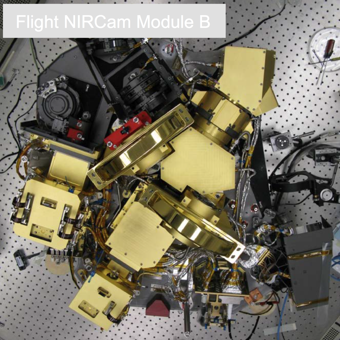
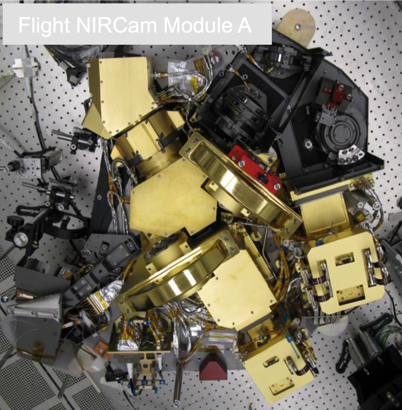
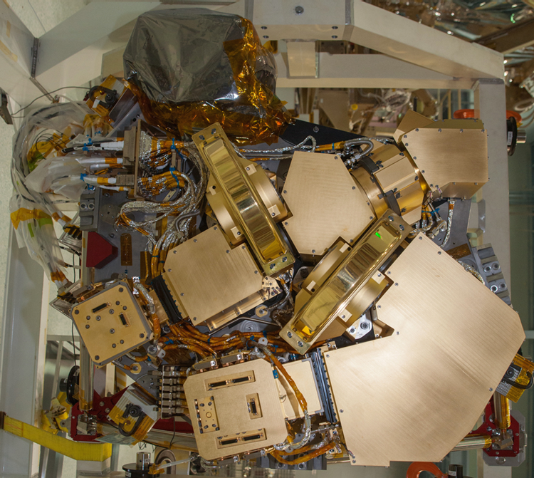
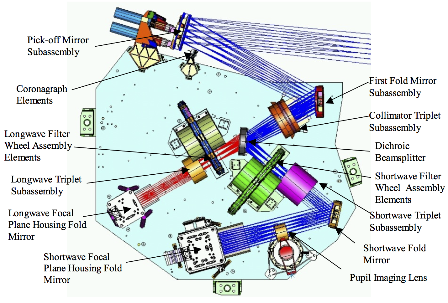
Views of the NIRCam modules
References
Greene, T., Chu, L., Hodapp, K. W., et al. 2016, SPIE 99040E
Slitless Spectroscopy with the James Webb Space Telescope Near-Infrared Camera (JWST NIRCam)
Greenhouse, M. et al. 2011, SPIE 814606G
Status of the James Webb Space Telescope integrated science instrument module system


