MIRI LRS Slitless Target Acquisition
Precise wavelength and flux calibrations of MIRI LRS data require accurate knowledge of the target's location on the detector. For time-series spectroscopy, a dedicated target acquisition (TA) exposure helps account for intra-pixel gain variations in multi-epoch transit observations. Users using the slitless mode are advised to perform TA as part of their observation to ensure that their target is placed with subpixel accuracy (<10 mas) at the nominal slit location. The pointing performance of the telescope is described in JWST Pointing Performance.
On this page
LRS slit and slitless modes each have their own custom TA procedures. TA is recommended for LRS slitless observations.
Please refer to LRS Recommended Strategies for concrete advice.
TA target
Typically, the science target is used for TA (i.e., self TA). For slitless time-series spectroscopy, most science targets will be bright and compact enough for self TA. However, users may also specify a bright, nearby point source as an offset TA target, provided that it lies within the APT visit splitting distance from the science target. For more information about choosing targets for LRS TA, see LRS Slit Target Acquisition - Self TA vs. offset TA.
TA filters and exposure settings
See also: MIRI Filters and Dispersers, MIRI Target Acquisition
Target acquisition for LRS slitless mode observations can use all filters, read modes, and observation settings described in the MIRI Target Acquisition article. The TA exposure is always carried out in a single integration. A signal-to-noise ratio > 50 is strongly recommended for successful TA.
Users should always use the JWST Exposure Time Calculator (ETC) to help choose the best TA filter and exposure settings for their science.
LRS slitless subarray and target acquisition region of interest (ROI)
See also: MIRI Detector Readout FASTR1, MIRI Optics and Focal Plane
Words in bold are GUI menus/
panels or data software packages;
bold italics are buttons in GUI
tools or package parameters.
Verification Image
To provide a reference for the location of the target in the subarray, a verification image should be taken at the end of the TA sequence, before the filter wheel is moved to the prism (P750L) setting. As of APT version 2023.1.1, TA verification images are no longer exclusively taken with the same exposure settings as the TA image itself. The user can specify any of the available imager filters and change the number of groups and integrations to obtain an optimally useful pre-image to the spectroscopic observation. The ability to edit the exposure configuration between the TA exposure and TA verification exposure is particularly useful in cases where an offset target is used for TA. While the acquisition of a verification image is optional, it is highly recommended to provide an astrometric reference for precise determination of the location of the undispersed source for post-processing.
Verification images no longer have to use the same filter as the TA observation, or be part of the TA sequence.
LRS slitless TA sequence
The sequence is as follows:
- The TA target is placed behind the focal plane mask, at the "TA BLOCK" location. This is to avoid saturation.
- The TA filter is selected in the filter wheel.
- The TA target is placed in the center of the LRS slitless ROI (SLITLESSPRISM_TA).
- An image is taken according to the APT specifications for filter, read mode, and number of groups.
- The onboard centroiding algorithm computes the centroid location of the target, and the offset to the nominal slitless pointing location is computed. This computation includes the offset to the science target, if an offset target is used for TA.
- The telescope executes a small angle maneuver (SAM) to place the target at the required location.
- An optional verification image is taken with the requested exposure settings.
- The science observation is commenced, which starts with moving the filter wheel assembly to select the double prism.
Exposures taken during the TA sequence are downloaded to the archive and made available to the observer.
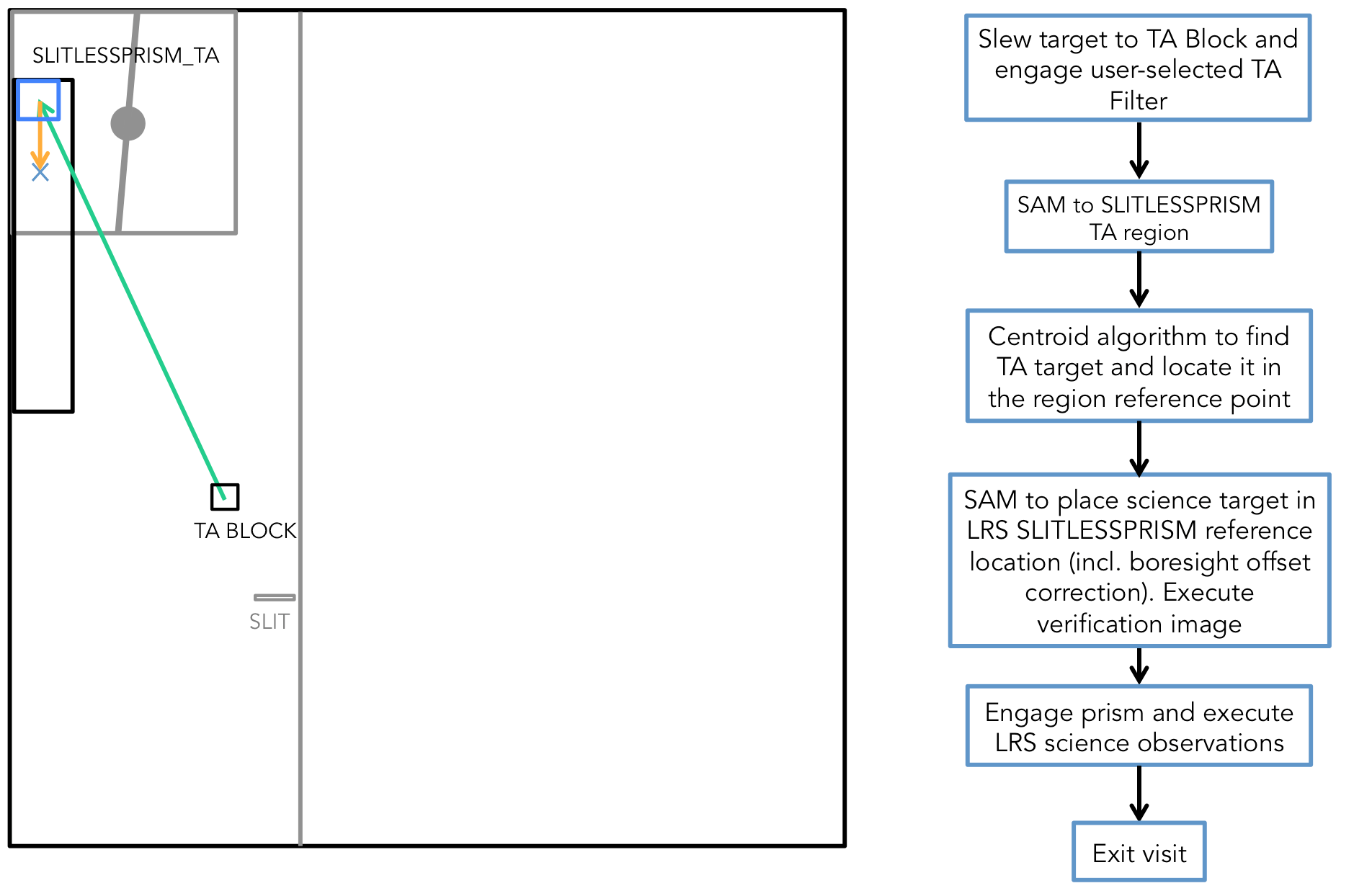
Click on the figure for a larger view.
Left: Diagram of the MIRI imager module focal plane. The blue box labeled "SLITLESSPRISM_TA" is the 48 × 48 pixels region of interest (ROI). The reference point is taken to be the midpoint of this ROI. Note the exact locations of these regions are kept in the Science Instrument Apertures File (SIAF). Right: Flow diagram describing the MIRI LRS slitless TA procedure. Note: the verification image step is optional, and may use different filter and exposure settings than the TA image.
Additional links
JWST ETC MIRI Target Acquisition