NIRCam Field of View

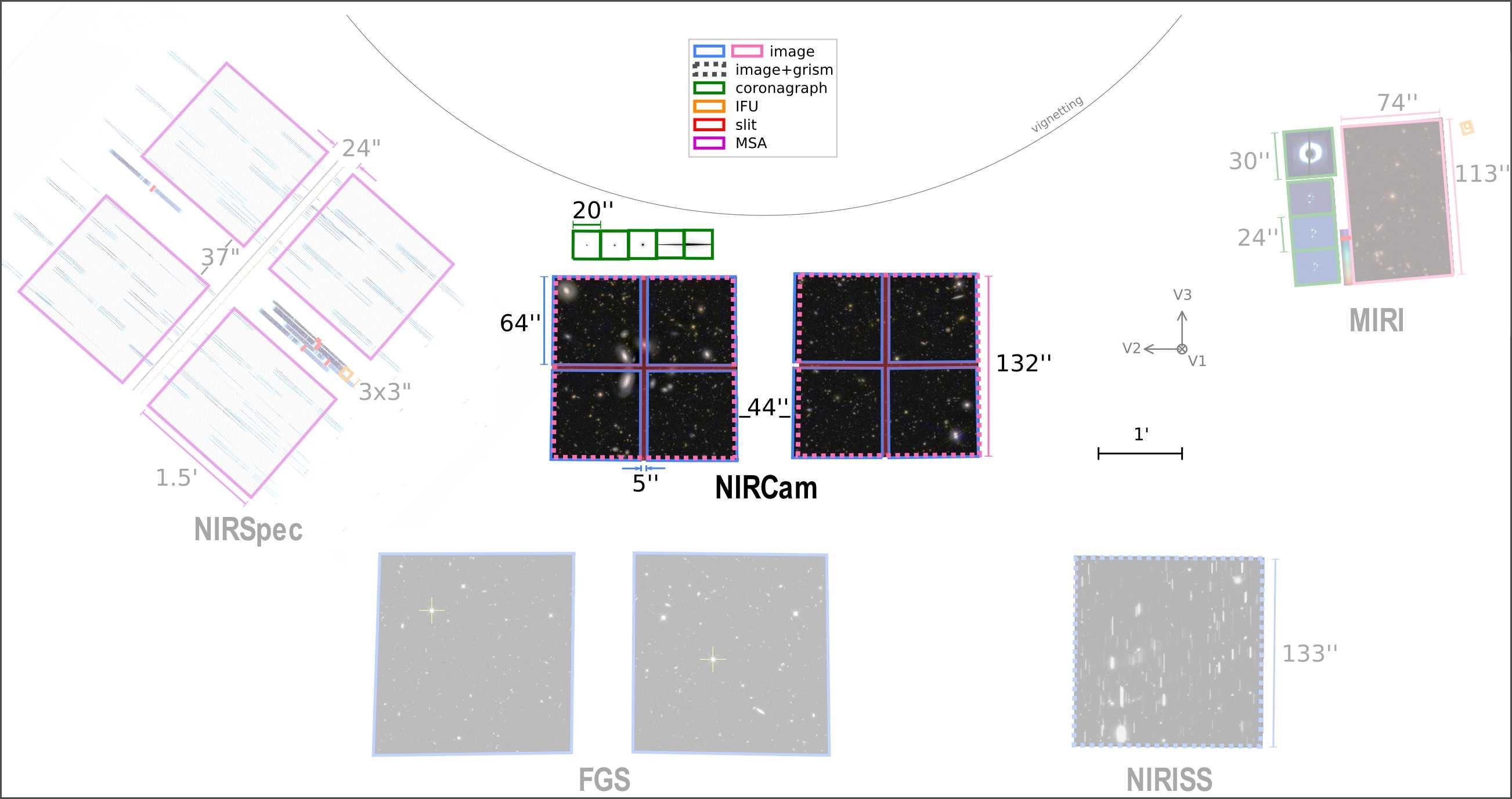
JWST's NIRCam observes a 9.7 arcmin² field with a ~44" gap separating two 2.2' × 2.2' modules. The short wavelength images also have 4"–5" gaps between detectors.

The full field of view may be imaged at short and long wavelengths simultaneously using dichroics. Short wavelength (0.6–2.3 µm) and long wavelength (2.4–5.0 µm) fields overlap well, but not perfectly.

Each module has 4 short wavelength detectors arranged in a 2 × 2 array and one long wavelength detector. The resulting short wavelength images have gaps of 4"–5" between detectors.

The gap between modules is 42"–44" for the short wavelength detectors and 45"–48" for the long wavelength detectors.  NIRCam primary dithers and mosaics may be used to cover all of these chip gaps.

Smaller subsections of the field of view may be observed by using NIRCam detector subarraysApertures define the pointing and extent of each observation in the field of view.


Field-of-view figures

Figure 1. NIRCam modules field of view
The NIRCam field of view in observatory coordinates (V3 up, V2 left). Observations may be obtained simultaneously with both modules using all 10 detectors at short (0.6–2.3 µm) and long (2.4–5.0 µm) wavelengths. The coronagraphs are used to image regions of the sky outside the imaging/grism field of view. When in use, these regions are projected onto the detectors by optical wedges located on Lyot stops in the pupil plane.
Figure 2. NIRCam in the JWST field of view
NIRCam in the JWST field of view
The JWST focal plane with highlighted NIRCam field of view, closest to the V1 optical axis of incoming light. Shown within each module are HST images (to scale) of GOODS-S from CANDELS and 3D-HST. The pink dashed regions show the 2 detectors for the long wavelength imaging/grism field of view. The 8 short wavelength detectors are outlined in blue. Above, in green, are the coronagraph subarrays with the occulting masks shown inside it. Those masks are physically located on the coronagraphic optical mount (COM), and images of the masks are moved onto the detector by an optical wedge co-located on the pupil wheel with the pupil-plane Lyot stops.


Notable updates
  •  
    Updated Figure 1 plot based on commissioning data. Alignment between SW and LW in module B has improved.
Originally published