NIRSpec Fixed Slits
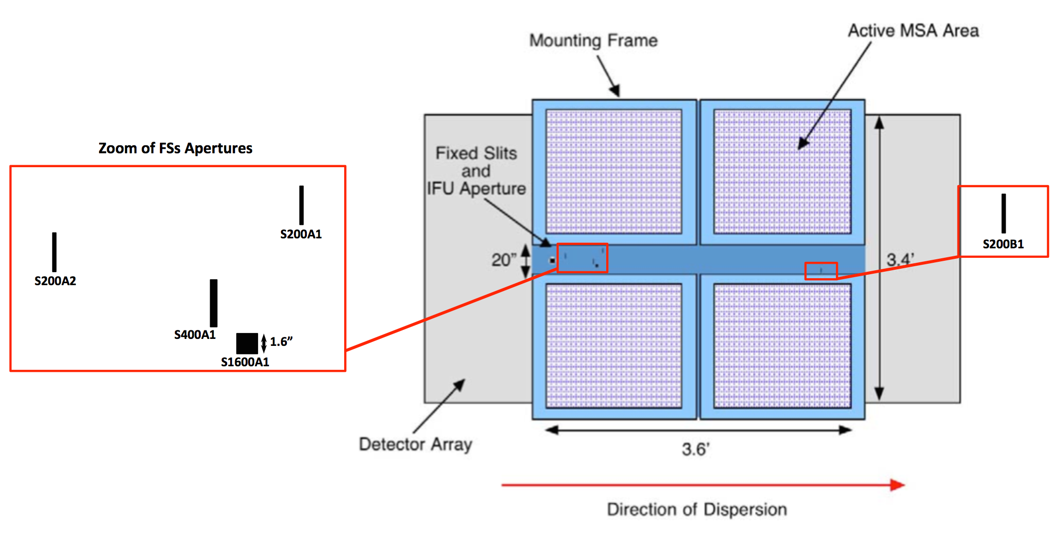
The NIRSpec fixed slits (FS) spectroscopy and bright object time-series (BOTS) spectroscopy modes use the 5 FS apertures machined into the mounting plate of the micro-shutter assembly (MSA).
On this page
NIRSpec has 5 fixed slits (FS) cut into the metal that separates the 4 micro-shutter assembly (MSA) quadrants. All apertures can be used in NIRSpec FS spectroscopy mode, but the 1.6" × 1.6" wide aperture alone is used for the bright object time-series (BOTS) observing mode. These FS apertures are always open, even if the multi-object spectroscopy (MOS) mode or integral field unit (IFU) spectroscopy mode is being used. By construction, the fixed slits spectra project onto a different part of the detector than the MSA or IFU spectra, and therefore there is no overlap or contamination from failed open MSA shutters. As a result, the FS can provide the most sensitive, highest-contrast spectroscopy available with NIRSpec.
Fixed slits positions on the MSA focal plane
Words in bold are GUI menus/
panels or data software packages;
bold italics are buttons in GUI
tools or package parameters.
Fixed slits dimensions on the sky
Table 1 presents the width and length of each fixed slit as projected onto the sky, as well as the naming convention. The name of each fixed slit also includes its width in mas. The 0.2" slits provide full spectral resolution, the 0.4" slit and 1.6" × 1.6 " apertures have spectral resolutions that are degraded by the spatial PSF or physical source size. The S200B1 slit is provided for redundancy. The S200B1 spectra can be truncated at long wavelengths, so this slit is not expected to be commonly used for science.
Table 1. Dimensions of fixed slits as projected onto the sky
| Fixed slit name | Width (arcsec) | Length (arcsec) | Note |
|---|---|---|---|
| S200A1 | 0.2 | 3.3 | |
| S200A2 | 0.2 | 3.3 | When used with S200A1, it provides full wavelength coverage across the inter-detector gap |
| S400A1 | 0.4 | 3.8 | |
| S1600A1 | 1.6 | 1.6 | High throughput slit used in BOTS mode |
| S200B1 | 0.2 | 3.3 | Redundant with S200A1 |
Fixed slits throughput
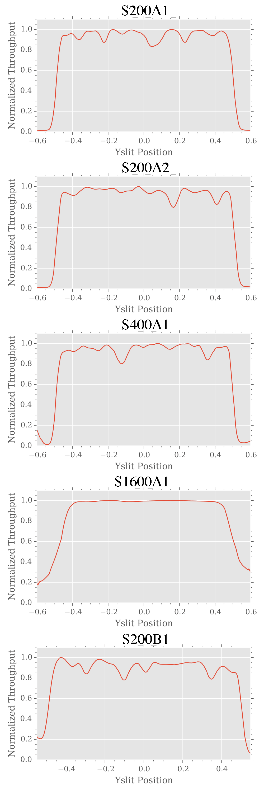
Like all slit-based spectrographs, the fixed slit apertures are not perfect rectangles. Due to their small physical sizes and the construction process, the fixed slit apertures have irregularities along their edges. These irregularities impact throughput and can affect spectral resolution and wavelength calibration. The locations of the rough slit edges are shown in Figure 2 (red circles), and 1-D curves of the average transmission along the slit length are shown in Figure 3. Note that the data reduction pipeline will take the actual transmissions of the slits into account. However, when combined with pointing uncertainty, these irregular slit edges can be sources of flux uncertainty for FS science. The FS nod offset positions has been updated to be slit-specific to avoid these irregularities and get the best possible throughput for point sources observed with the FS. The S1600A1 aperture is wide enough that it is not significantly affected by these throughput issues.


