NIRSpec MOS Recommended Strategies
The recommended strategies for the JWST NIRSpec MOS mode depend largely on science use case and goals. The emphasis here is on universal tips and tricks to improve observation efficiency, and avoid common problems.
On this page
Words in bold are GUI menus/
panels or data software packages;
bold italics are buttons in GUI
tools or package parameters.
For step-by-step instructions see the JWST Multi-Object Spectroscopy Roadmap.
How MPT operates, and what it produces
See Also: MOS terminology
MOS planning with the automatic planning tool (MPT) is recommended for most MOS science. The tool makes use of the instrument model to find accurate source positions at the MSA, and it uses the shutter status information to avoid inoperable shutters, to name a few of the issues that affect MOS observation planning. Using the tool to define your MOS observations is recommended for all but some specialized science cases. MPT can plan observations at a single pointing, or at multiple dithered pointings. With a proper Catalog and sufficient source coverage, MPT will derive favorable pointings and matched MSA Configurations at those pointings for the user. In this case, the observed sources are not precisely defined by the user - MPT selects them at optimal pointings that it determines for the observation. MPT can also be used to create an MSA Configuration at a fixed pointing that the user chooses. The MPT computational requirements and performance are given in NIRSpec MPT - Computational Performance.
Feasible angles
See Also: MOS and MSATA Observing Process
There are convenient tools for identifying feasible Aperture Position Angles (APA) for a given target or pointing for JWST observations. They are the General Target Visibility Tool (GTVT) and the NIRSpec Observation Visibility Tool (NOVT). Note that the APA and V3PA are not the same for NIRSpec, but are related.
Catalogs and Candidate lists
See Also: MPT - Catalogs
All MOS observation planning with MPT must be done using a Catalog. 'Primary' or 'Filler' candidate lists are derived from the parent Catalog.
Each MOS observation can only be planned using a single parent Catalog. Plans derived from different Catalogs can only become separate observations.
Catalog size and field of view
See Also: Resources for MOS and MSATA Program Updates, NIRSpec MSA Target Acquisition, NIRSpec MSATA Reference Star Selection Recommended Strategies, Predicting MSATA Reference Star Magnitudes
When preparing for proposal submission, it is useful to work with a Catalog in MPT in order to experiment with observing strategies and get a realistic estimate of the observing efficiency of your MOS observation. If a catalog from HST or JWST/NIRCam imaging is not available for your target field (e.g., you are planning to also request NIRCam pre-imaging to obtain a Catalog with accurate positions), then you should create a fake Catalog of expected size and density for running MPT.
When observing with the MSA and using the MSATA methodology for target acquisition, the Catalog area should minimally cover the MSA footprint. This area is approximately 3.5' × 3.5'. Particularly for detailed program updates, the coverage should be large enough to provide the flexibility of planning at any Aperture Position Angle (APA). This is especially true given that the APA will be assigned to most MOS programs. The extra Catalog coverage will provide some flexibility to MPT to find preferred pointings where a greater number of sources can be observed at a given APA in a single pointing, or over a set of defined dithers. Additionally, it will serve to provide reference stars for the MSATA over the 4 MSA quadrants at different orientations. Reference stars must be defined in the program update, but are not needed at proposal submission.
If you have a real Catalog or candidate set (e.g., from HST or JWST/NIRCam) covering an area that is smaller than the MSA footprint, and plan to use the high resolution gratings, try to design your plans so that the majority of the sources are in quad 3 and quad 4. This helps to ensure that the target spectra will not be cut off by the edge of the detector. You can do this by adjusting the search grid parameters in the MPT Planner with a fixed APA.
Source weights
See also: MPT Planner
If some Catalog sources are preferred over others, place them at the top of the Catalog. This will ensure that these sources are considered first for the MSA Configurations, even when target weights are not used. Both Primaries and Fillers are added into an MSA Configuration in the order they appear in the Catalog. Source weights can also be added to the Catalog and used during planning. If weights are used in planning, the candidate sets will be ordered by weight before considering them for the MSA Configuration. The weights can be a positive float value, and should reflect the relative preference for observing them. Weights up to a very large maximum value will be read correctly. However, to avoid problems with MPT selecting the best pointing using summed weights, is recommended to use a more conservative maximum Weight value of 1e9 in practice. During planning, the candidate lists will be ordered by the source weights.
When a user chooses to use source weights in planning, the weights of observed Primaries are used to define the best pointing, and the weights of all observed sources, Primaries, Fillers, and Contaminants are summed into a Total Weight for each exposure in the Plan.
Excluding Reference star candidates from the science source candidate sets
See also: MPT - Catalogs
Reference stars can be optionally excluded from a Candidate set when filtering to create a new Candidate set. There is now a filter called Reference Star filter that can be used alone or in combination with other filters when designing a new Candidate set.
Observing the same sources over a set of dithers
See also: MPT Planner
Like the Primary sources, Fillers are tracked during dithering so that MPT Plans with dithers will observe both Primaries and Fillers at as many dither points as possible. This is the default behavior of MPT. The set of observed sources may not fill the MSA, but each source will have been observed for the maximum exposure depth.
Alternatively, many observers may be interested in observing as many Primary sources as possible, even if they are not observed to the full exposure depth. This can be done when using Fixed Dithers by also selecting the option Partially Completed Sources in the MPT Planner.
If you would like to fill the MSA with as many preferred sources as possible at each dither, it is recommended to select Partially Completed Sources when dithering. If selected, after a first round where MPT selects Primary sources that can be observed at all dither points, it will look for additional Primaries at as many dither points as possible (down to a minimum number of exposures specified by the user). After completing the addition of extra Primaries to varying depth, the Fillers will be added in the same manner; completed Fillers will be added first, followed by Fillers at fewer and fewer dither points. This option will help to maximize the use of the MSA, though some sources will be observed at less than maximum exposure depth.
Primary and Filler candidate lists can be created from filtering on column values in the parent catalog. If that cannot be easily done, then another way to do this is to add a column to the parent Catalog with a '1' for Primaries and a '0' for Fillers. Upload the Catalog, and then create the Primary and Filler candidate sets by filtering using the added column. When ingesting the Catalog, be sure to label the column as a "Number" type column in the pull-down menu.
Using "stuck-open" or "failed-open" shutters
See Also: MPT Planner, NIRSpec MSA Shutter Operability, NIRSpec Background Recommended Strategies, NIRSpec MSA Leakage Correction for IFU Observations, NIRSpec MSA Leakage Subtraction Strategies
The spectrum of the sky or any discrete source falling into a failed-open shutter is dispersed onto the detector, and this could overlap with the spectrum of one of your science sources. Whether this is significant for your science will depend on the brightness of your source, the grating used, and the background flux level as a function of wavelength. The zodiacal background at a given pointing can also vary depending on the time of year. Normally, MPT will not allow planned sources from the Primary or Filler candidate sets to be observed in stuck open shutters, as they are poorly calibrated. However, an unplanned source from the Catalog can inadvertently land in one of these stuck open shutters. This will usually not pose a problem because the default of MPT is to prevent spectral contamination of nearby planned sources by masking out all the shutters around it that could contaminate other source spectra.
Optionally, MPT can be instructed to use stuck-open shutters for planning to increase the multiplexing in the MSA for a given exposure. Not only will the stuck-open shutter itself become available, but nearby shutters that would normally be masked to prevent spectral contamination by a source in the stuck-open shutter will also become available for planning. In the MPT Planner, there is a checkbox called Allow sources in areas affected by stuck open shutters. See Figure 4. Select this option to allow MPT to use these shutters for planned (Primary and Filler) sources.
When using this option, there are some trade-offs to keep in mind. First, the photometric calibration of a source in a failed-open shutter will be less certain. Secondly, even if there are no planned sources in the failed-open shutter itself, the spectrum of a planned source in a nearby (normally masked) shutter will be affected by light entering the stuck-open shutter. That may be sky background light, or light from an unplanned (Catalog) source that is not a Primary or Filler Candidate. Its spectrum will be shifted in dispersion with respect to that of the science source. Of course, the impacts can only really be assessed after the APA has been assigned. Also, using this option may only provide a few additional sources to the Plan. For these reasons, users who require well-calibrated fluxes should not use this option. Whether or not this option is selected, MPT will attempt to prevent spectral contamination by separating planned sources (i.e., those from the Primary and Filler candidate sets) in the MSA.
Users who are considering this option may find the article on Background Recommended Strategies useful for estimating the impact of background contamination. The article Background Limited Observations gives advice on how to use the ETC to assess if your observations are sensitive to time variable background levels.
Avoiding contamination by other sources in the slit
See Also: MPT Planner, NIRSpec MPT - Plans, Custom MOS Observations using the MSA Configuration Editor
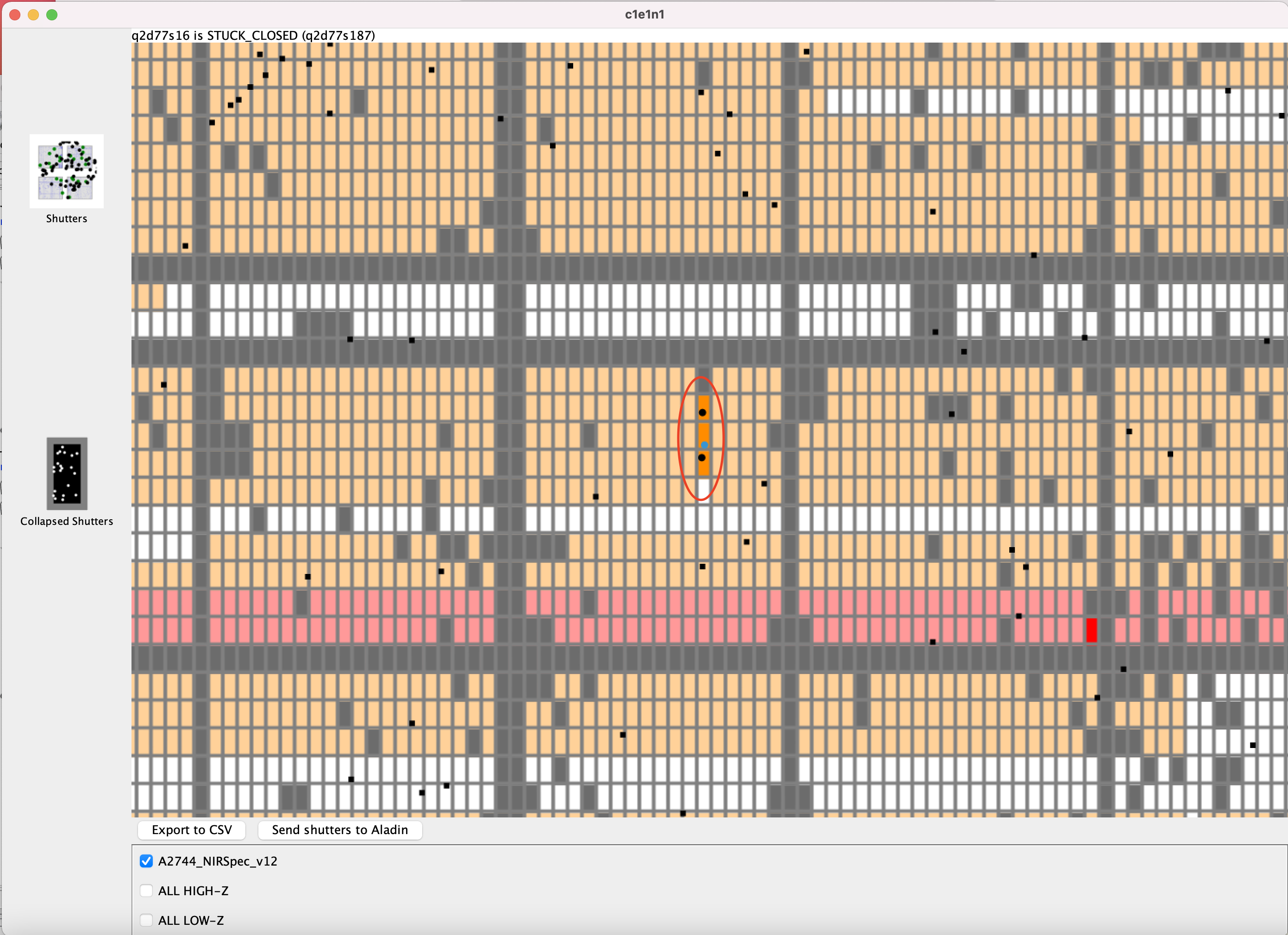
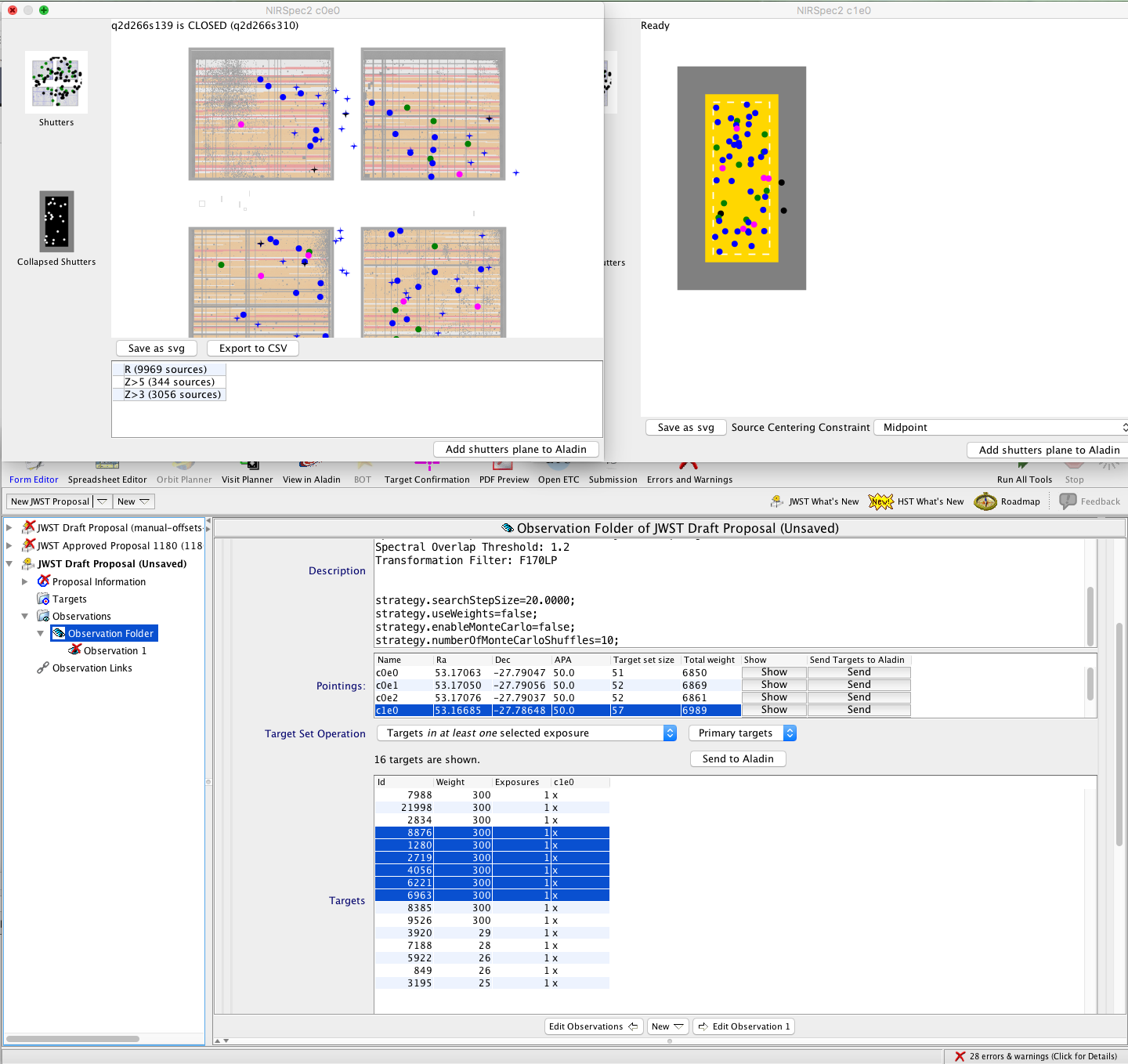
The Catalog should include not only your desired sources, but all other sources in the field, so that contamination from unplanned sources can be checked. Contamination checking must be done after a plan has been created in MPT. You can check a planned exposure (in the Plans tab of MPT) by bringing up the MSA Shutter View, and loading the parent Catalog from a checkbox displayed below the shutters. This will display all additional sources on top of the observed sources with different symbols. Look for slits that have more than one source within the (dark orange) planned slit. These unplanned sources are shown as black symbols (Figure 1). If you find some affected slits, either re-plan after lowering the weight of the target source in the Catalog or, if weights are not used, move these affected sources lower in the Catalog. Alternatively, you can use the MPT's MSA Configuration Editor to select alternate targets in the MSA Configuration, but that approach is tedious.
Observing a set of sources with multiple dispersers
If the goal is to observe the same sources with more than one disperser, it is usually preferable to plan them together in the same MPT Plan to ensure the the same MSA Configurations are observed with each.
Alternatively, one may prefer to create separate MPT Plans is to maximize the number of sources for the PRISM exposures. PRISM spectra are much shorter and it is possible to observe 3 or 4 times more of them at a single pointing (if the Catalog density is high). When planning independently, there are no proven strategies to ensure that a large number of the same sources are observed in both Plans. One way to attempt this is to design the grating Plan first, and export the list of observed sources. Increase the weights of the successful sources in the Catalog, then re-import it, and make two new Plans, one for the PRISM (which will use PRISM multiplexing) and one for the grating or gratings you want to observe. The altered imported Catalog must become the new Catalog from which all derived Plans are generated. The new Plans can be selected together in the MPT Plans pane to create a single observation in the MOS spectroscopy APT template, as described in the section Merging Plans for overhead savings.
There are few choices for planning high- or medium-resolution grating spectroscopy in conjunction with PRISM spectroscopy:
- Make separate Plans to make the most of MSA multiplexing for each. This will likely result in many fewer sources in common in both Plans. The user then has the option of altering the Catalog weights during planning as described above.
- Plan them together so that more of the same sources are observed in all dispersers in the same Plan. First, select all the desired dispersers when generating the Plan in MPT. Then, you have 2 choices:
- Checking the box Multiple Sources per Row in the Planner will result in the use of the PRISM multiplexing, but will also cause overlapping spectra for the grating exposures. You can additionally specify a Minimum Separation in shutters to control the extent of spectral overlap.
- Not checking the box will result in the appropriate multiplexing for the gratings to avoid overlapping spectra, but will generate PRISM exposures with fewer sources.
Merging Plans for overhead savings
See Also: Custom MOS Observations using the MSA Configuration Editor
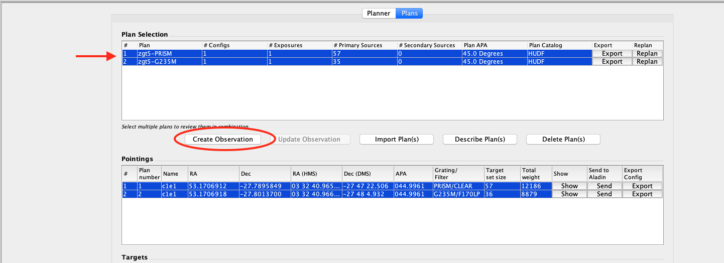
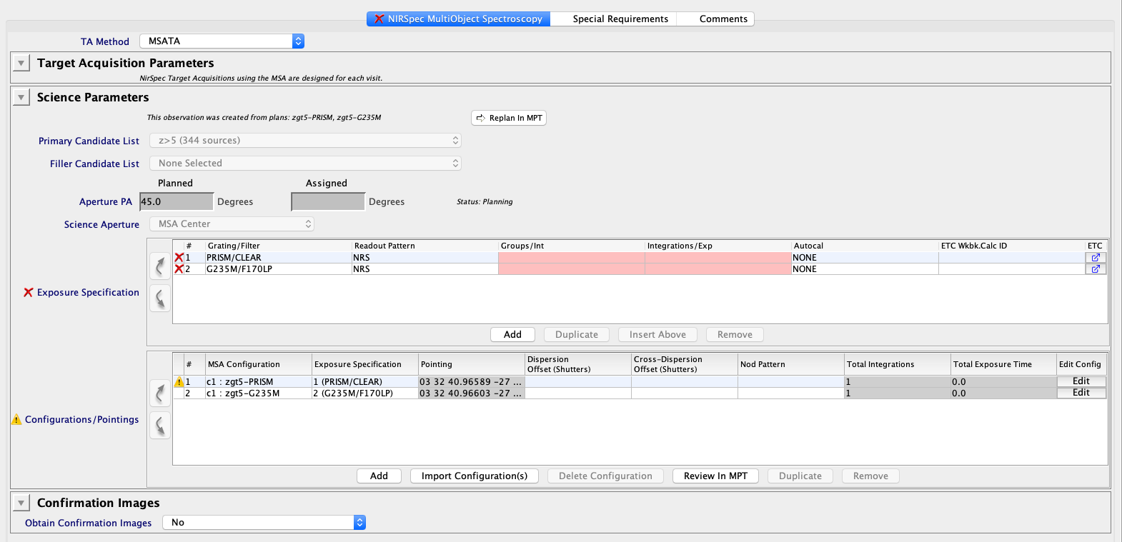
After developing a set of Plans in MPT, or designing a custom MOS observation in the MOS spectroscopy template, it is possible to select the associated Plans in MPT on the Plans pane and merge them into a single observation in APT using the "Create Observation" button. The plans must all have been designed using the same Aperture Position Angle, and must originate from the same parent Catalog, or merging will fail. Merging plans into one observation can save overheads like the GS acquisition overhead by more efficient packing of the visits where possible. This feature, shown in Figures 2 and 3, can be used for merging multiple MPT-generated Plans, like those described in option 1 of the previous section, or for merging plans from MOS observations designed at the observation level, or both.
When merging plans, the individual plans that went into the resultant merged observation should be saved in MPT. Doing so will allow for re-creating these observations when needed, and will help reviewers to understand how the merged plan was created. Unfortunately, the "Describe Plans" button (Figure 2) does not capture the individual plan parameters of an observation made by merging plans.
Exposure parameters
See Also: NIRSpec Detector Recommended Strategies, JWST ETC, MOS observation template
Follow the prescribed recommendations in NIRSpec Detector Recommended Strategies and use the JWST ETC to best determine exposure parameters (Readout Pattern, Groups/Int, Integrations/Exp, seen in Figure 3) that balance exposure overheads and cosmic ray hits. The maximum recommended integration duration is 1,500 s. For deeper observations, additional duplicate exposures can be specified in the MOS observation template Configurations/Pointings area to obtain the total exposure time needed on sources. It is also possible to adjust the exposure duration parameters in the Exposure Specification area of the template. The editing buttons for these tables are activated when an exposure specification is highlighted.
Creating a fixed pointing in MPT
See Also: NIRSpec MPT - Planner
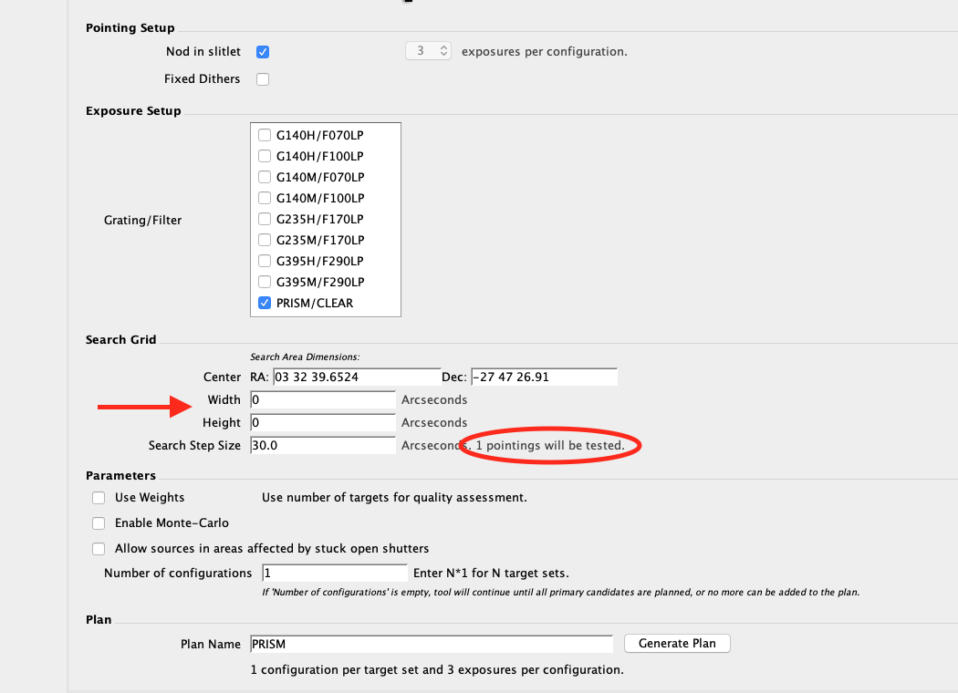
To make a plan at a fixed pointing, insert the pointing corresponding to the Center of the MSA and set the search grid Width and Height to 0" in the MPT Planner, but make sure the Search Step Size is non-zero. See the figure below. MPT will design the associated MSA Configuration for the Primary and Filler Candidate Sets in an optimal way using the fixed pointing and APA specified in the Planner.
If it is not strictly required for your science, allowing the MPT some flexibility in planning the pointing is usually preferred for obtaining a more optimal solution. You can adjust the Search Grid parameters to search a small area around your preferred pointing, with a fine search grid. Depending on your Catalog density among other factors, MPT may find a pointing which will observe more of your candidate sources.
Dithering strategies
See Also: NIRSpec MOS Dither and Nod Patterns, NIRSpec Dithering Recommended Strategies
Dither and Nod options for MOS spectroscopy are described in NIRSpec MOS Dither and Nod Patterns.
Dithering is highly recommended for observing with the MSA. In the MPT, pre-defined dither patterns are not offered as they are for other APT templates. Instead, the user specifies a set of fixed dither separations, and the specific pointings are derived for the user by the MPT. Multiple dithers can be specified, and each will result in a new exposure (or set of exposures, if nods are specified). Fixed Dither requires an integer number of shutters to be specified, but the algorithm can accept short or long dithers.
It is important to note that optical distortions cause individual sources to be offset by slightly differing amounts, especially when dithering over large distances (>~ 10"). However, MPT will calculate the individual positions of the sources after a specified dither taking these distortions into account, and will create a new MSA Configuration in order to observe all the Primary sources at the new offset position. As a result, individual sources may be dithered by a slightly smaller or larger distance than specified, thereby assuring that sources line up with their respective shutters. This approach helps to increase the multiplexing of the MSA when dithers are used.
Bridging the detector gap
See Also: NIRSpec MOS Wavelength Ranges and Gaps, NIRSpec MPT - Planner
A dither of ~20" (80 shutters) or larger in dispersion (2 or more exposures) will provide enough separation to bridge the detector gap, so that combining spectra from the 2 dither positions will fill the wavelength gaps. This can be done in a few different ways: (1) Specifying a fixed dither of 80 shutters in the dispersion direction in the MPT Planner, (2) Specifying a plan in MPT using the No Gaps checkbox in the MPT Planner, or (3) Specifying a dispersion offset directly in the Configurations/Pointings table in the observation template.
In the default operation of MPT, primary sources will not be observed in regions of the MSA where there is no overlap between pointings. These areas can be filled by specifying a Filler candidate list during planning. Additionally, it is now possible to add in Primaries and Fillers that will be observed in one or more exposures, but which are not completely observed at all specified dithers. This is accomplished by selecting the option for Partially Completed Sources in the MPT Planner. This checkbox is offered in MPT only when one or more dithers are specified in the Planner.
Sub-shutter dithers
See Also: NIRSpec MOS Wavelength Ranges and Gaps, NIRSpec MPT - Planner
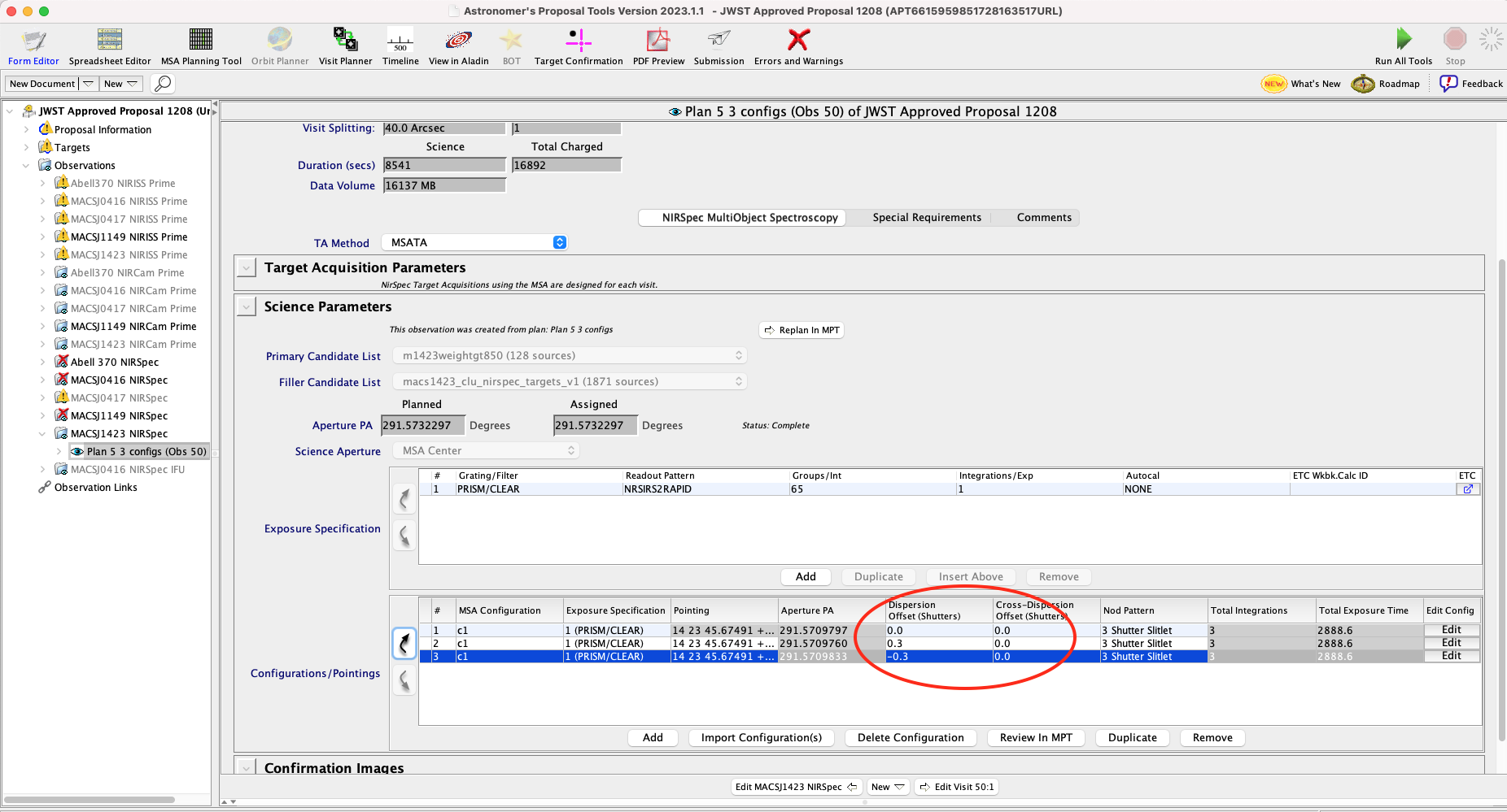
A sub-shutter dither can be specified directly in the Configurations/Pointings table of the MOS observation template. Each dither point is specified in a different row of the table, and results in one additional exposure, if no nods are added. Start with an exiting Plan (e.g., perhaps one created with a catalog using MPT from which the observation is created). This will create a row for the base pointing in the Configurations/Pointings observation table. Highlight the row and duplicate the entry for the base pointing using the Duplicate button below the table. Using the Dispersion and/or Cross-dispersion Offset columns in the table, specify fractional shutter dithers for the new row, as shown in Figure 5. The process can be repeated if additional sub-shutter dithers are desired. Finally, adding nods using the Nod Pattern column will then create multiple additional exposures for each dither specified. Depending on each source's placement in its respective shutter, even a sub-shutter dither could place a source behind the bar separating MSA shutters.
Nods
See Also: NIRSpec MOS Dither and Nod Patterns
Short in-slit nods are appropriate for point-like sources, but are not recommended when MSA sources are extended (e.g., when they fill the shutter). Nods are generated by MPT when the user clicks the button of the same name in the MPT Planner. Alternatively, nods can be added to a MOS exposure directly in the Configurations/Pointings table of the MOS observation template using the Nod Pattern column of the table, as shown in Figure 5. Nodding will obtain independent measurements of point-like sources in spectral bands I or II that can be combined to increase signal to noise. The number of exposures that result will be a multiple (e.g., 3, for 3-nod positions) of the number of specified dithers for each exposure specification (i.e., each grating-filter combination that is specified in the plan). For band III, the PSF is broader than one shutter, so in this case, if nodding is desired, the longer 5-shutter slitlet can be used with nodding at 3 positions in the slitlet. Further, constraining the source centering using the MPT Source Centering Constraint parameter should help to limit source flux from leaking into nearby shutters.
Slit-stepping or Slitlet-stepping: Pseudo-IFU MOS observations
See Also: Long Slit MOS Observations, Custom MOS Observations using the MSA Configuration Editor, NIRSpec TA Recommended strategies
There are several reasons why an observer may want to step a slit or slitlet across a source or sources in the MSA to create pseudo-IFU observations: slitlet stepping can help to ensure on-source exposures when the coordinate accuracies are less certain than otherwise required for MOS observations with the MSA, or when the target acquisition methodology MSATA cannot be performed, for one reason or another.
The slitlet-stepping strategy with TA Method = NONE may be considered as a last resort for crowded fields where MSATA is not possible.
Often the science targets have resolved structure and observers may wish to perform slit-stepping (with a long slit across an extended source) or slitlet-stepping (with an MSA Configuration of small slits on a distribution of sources in the MSA) to create pseudo-IFU exposures. It is more efficient to dither the telescope between steps using the same MSA Configuration rather than to hold the telescope pointing fixed and re-configure the MSA at each step.
For very extended sources, one may wish to use the long slit configuration and step across the source in the dispersion direction, for example.
For a distribution of slightly-extended sources across the MSA, the preferred approach is to design an MSA Configuration automatically in the MSA Planning Tool using a Catalog. Alternatively, one may use the MSA Configuration Editor at the observation level in APT to design an MSA Configuration. Either way, the next step is to create duplicate exposures in the MOS observation template. In the duplicated exposures, different offsets can be specified in the dispersion direction to effectively create a set of pseudo-IFU exposures. Normally, one would specify offset positions on either side of the initial position. In this science case, MSATA may not be necessary; TA Method = NONE may be sufficient. In the case of small slitlets stepped over a distribution of MSA sources whose centers are listed in a Catalog, the slits of some exposures will not contain the source centers. To avoid pipeline problems, empty slits will be assigned fake sources at the center of the center-most shutter. Note that these data will not be associated automatically in the pipeline—the observer will need to reprocess the observation.
Examining MOS observation and MPT Plan results
See Also: NIRSpec MPT - Plans
Plans generated in the MPT, or MOS observations turned into Plans can be examined in the MPT Plans tab. The latter process is described in the NIRSpec MPT - Plans article. Once in the Plans pane, MOS targets can be highlighted and the same targets will also become highlighted in other views ('MSA shutter view' and 'Collapsed shutter view'). Make sure to first highlight or select one or more Plans, and one or more Pointings before highlighting the targets of interest. Also, clicking on a target in either the MSA Shutter View or the Collapsed Shutter View will highlight them in other views. See Figure 6.
Planning information about sources in the exposures can also be exported from MPT. From the APT menu, select File → Export → MSA Target Info (csv).
Adding NIRCam or MIRI parallels
See Also: Coordinated Parallel Dither Tables
When adding NIRCam parallels to NIRSpec observations, the NIRSpec observations will typically drive the pointing selection. Dither patterns can be added for the NIRCam parallels to improve sampling in the images. The patterns are described in the article Coordinated Parallel Dither Tables. Some considerations concerning exposure time matching of the parallels and the Primary observations are described below.
It is important not to specify any auto-cals (designated Autocals in APT) for the NIRSpec observations as these are incompatible with the parallels that will be added after the NIRSpec planning is completed. Auto-cals are not recommended for most science programs, with or without parallels.
An example use case, NIRSpec MOS Deep Extragalactic Survey, describes planning NIRSpec MOS from an existing Catalog and adding NIRCam parallels for nearby imaging.
Compromise dithers and exposure time matching of parallel instruments
See Also: NIRSpec MOS Operations - Pre-Imaging Using NIRCam
There are a few optional dithering choices offered with the addition of the NIRCam coordinated parallels. Two- or 3-point "compromise" dither patterns, in 3 different possible separations each, may be selected via the Dither Type parameter in the Science Parameters section of the template once the NIRSpec observations are defined. Adding these dithers will double or triple the NIRSpec exposures. NIRSpec planning should be done with this in mind, but it is possible to adjust the exposure duration parameters of NIRSpec after the fact.
Note that there needs to be an exact match between the number of NIRSpec exposures and the number of parallel exposures, and the parallel exposures must be shorter than the NIRSpec exposures. The exposure duration parameters for the NIRSpec exposures may be altered if NIRCam parallels are added with compromise dithers.
If you are planning to add NIRCam parallels and wish them to become the pre-imaging for follow-up NIRSpec observations, be aware that there are Special Requirements that should be added to the NIRSpec observations. These are outlined in NIRSpec MOS Operations - Pre-Imaging Using NIRCam.
Crowded fields
See Also: JWST Cycle 1 Observation Mode Restrictions, JWST Pointing Performance, MSA Target Acquisition, NIRSpec Target Acquisition Recommended Strategies
Note in the Call for Proposals the observing restriction for crowded fields needing MSATA.
NIRSpec observations that require the MSA-based target acquisition in fields with a high density of targets (>~1 star per sq. arcsec) that are measurable in MSATA images, or with many bright targets (<ABMag 19.1 at higher density than 1 star per 10 sq. arcsec) are not permitted.
There is a greater likelihood of failure of the MSATA process that uses reference stars to align the pointing when reference stars reside in crowded fields, or are saturated. Consult the NIRSpec Target Acquisition Recommended Strategies article for more information about this, and about other possible TA strategy selections for MOS in crowded fields.
Extended sources
See Also: Long Slit MOS Observations, Custom MOS Observations using the MSA Configuration Editor, NIRSpec Target Acquisition Recommended Strategies
Spatially extended targets of tens of arcseconds to an arcminute or more can be observed using the NIRSpec MOS mode. These observations are accomplished by positioning sources in the left side (quadrant 3 and/or 4 (Q3, Q4)) of the MSA field of view. Positioning these extended targets in Q3 or Q4 affords the best chance of getting complete spectra unaffected by the long wavelength detector cutoff. The MSA planning Field Points in quadrant 4 of the MSA are offered with TA_Method = NONE, Verify_Only, or the wide aperture target acquisition (WATA) strategy as an alternative to automatically generating planned observations using the MPT. The process of specifying such an observation directly in the MOS template (without using the MPT) is described in the article Custom MOS Observations using the MSA Configuration Editor. Additionally, 2 built-in long slit MSA Configurations are offered in the pull-down for the MSA Configuration in the Exposure Specification. One of the 2 long slits can be used with the corresponding 2 Q4 field points in the Science Aperture selection. The process of using the built-in long slits is described in the article Long Slit MOS Observations.
Moving targets
See Also: Long Slit MOS Observations, NIRSpec Wide Aperture Target Acquisition, JWST Pointing Performance
Moving targets can pose a challenge for NIRSpec MOS, but they are feasible to observe with special constraints. Particularly, the standard target acquisition process, MSATA, using nearby reference stars will not work because reference stars will be moving with respect to the stationary moving target tracking. Instead, moving targets with the NIRSpec MOS may use blind pointing (TA_Method = NONE) or the wide aperture target acquisition (WATA) strategy if the source is compact with a measurable centroid. The process of planning an observation directly in the MOS template (without using the MPT) can be used for moving targets; this is described in the article Long Slit MOS Observations.
