NIRSpec Integral Field Unit
The JWST NIRSpec integral field unit (IFU) hardware uses an image slicing mirror design to deliver spatially resolved imaging spectroscopy.
On this page
NIRSpec's IFU can obtain spatially resolved imaging spectroscopy of a contiguous 3" × 3" area on the sky. To achieve this, the IFU uses specialized optics to reformat the spatial field of view and direct light to the spectrograph optics, which are shared with the multi-object spectroscopy (MOS) and fixed slits (FS) spectroscopy observing modes. This page describes NIRSpec hardware components that are specific to the IFU observing mode.
The IFU entrance aperture
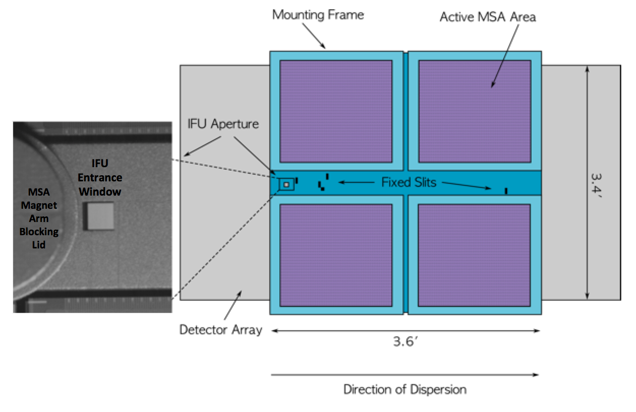
Light enters the NIRSpec IFU through a square entrance aperture that is machined into the metal separating the 4 quadrants of the micro-shutter assembly (MSA). Figure 1 shows the location of the IFU aperture in the NIRSpec field of view. The zoomed view to the left shows a photograph of the IFU entrance. The magnet arm that is used to configure the MSA has a small semi-circular extension—a "blocking lid"—which acts as a shutter and prevents light from entering the IFU when the IFU is not in use (shown in blue in Figure 2). This magnet arm moves to a different position to uncover the IFU entrance aperture when the IFU is selected for science.
In any NIRSpec imaging observations used for target acquisition or position verification, the IFU will be configured open to also acquire field images through the IFU optics.
IFU optics
See also: NIRSpec Optics
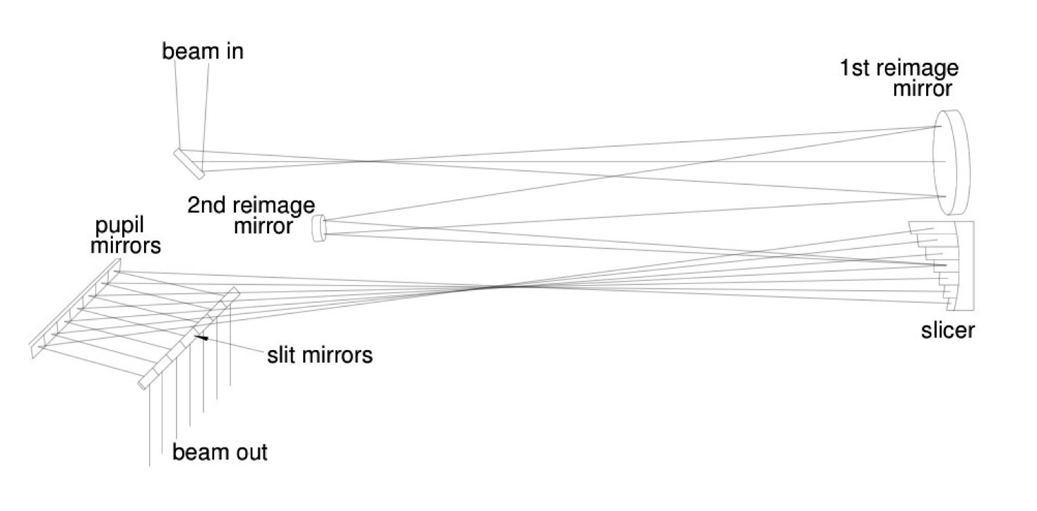
In addition to the spectrographic components described in the NIRSpec Optics article, the IFU includes specialized optics to carry out 3-D imaging spectroscopy (see the optical schematics in Figures 3 and 4).
After the light enters the IFU aperture, 2 re-imaging mirrors form a magnified image of the source field on the image slicer. The NIRSpec IFU image slicer (Figures 4 and 5) consists of 30 stacked mirror surfaces. Each is curved and tilted differently, sending the slice reflections on to 2 additional mirror arrays, the pupil mirrors, and slit mirrors (see Figure 4). The pupil mirrors are curved and tilted to align the slice images with the slit mirrors. The slit mirrors are also curved and tilted so that the aligned and stacked IFU slice images are directed towards the spectrograph entrance to the grating wheel assembly (GWA).
In this way, a 3.0" square region is rearranged into the stack of 30 spectra in the IFU data view. Each of the 30 spectra maps to a spatial region on the sky that is 0.1" wide and 3.0" high. Half of the spectra are directed towards the upper half of the detectors, away from the MSA frame and fixed slits, and the other half are directed towards the lower portion (see the IFU data view). The IFU optics magnify the image slices by a factor of about 2 in the dispersion direction, so that unresolved spectral emission features will appear 0.2" wide (2 pixels) on the detector. This gives about the same spectral resolution as the NIRSpec MOS mode and avoids undersampling the line spread function.
The IFU mapping from in-field slice position to detector spectral location is shown in the IFU data view. Each IFU slice puts the spectrum on a different part of the detector. Cross-talk between slices is less than 5%.
References
Closs, M., Ferruit, P., Lobb, D. R. et al. 2008, Proc. SPIE, v. 7010, 701011-1
The Integral Field Unit on the James Webb Space Telescope's Near-Infrared Spectrograph
Dorner, B., Giardino, G., Ferruit, P. et al. 2016, A&A, 592, A113
A model-based approach to the spatial and spectra calibration of NIRSpec onboard JWST


