MIRI Imaging Mosaics
The imaging mode for JWST’s Mid-Infrared Instrument (MIRI) offers a mosaicking option for coverage of larger fields of view (FOV) that extend beyond a single pointing.
On this page
Observers Resources
See also: Specifying Mosaics in APT
See also: APT Mosaic Planning, JWST Mosaic Overview
How to implement MIRI Imager mosaics
Mosaics for MIRI imaging observations can be implemented in the Astronomer's Proposal Tool (APT) with the JWST APT MIRI imaging template. These mosaics provide coverage of larger fields of view (FOV) that extend beyond a single pointing.
Words in bold are GUI menus/
panels or data software packages;
bold italics are buttons in GUI
tools or package parameters.
Starting with the first tile in the mosaic, the exposures are carried out at each dither step, and the filter changed once the dither pattern has been completed. Once all the user-specified filters have been rotated through for a single tile, the sequence is repeated for the next tile, and so on.
For MIRI imaging mosaics, each tile will usually be a separate visit that requires its own guide star. This depends both on the overlap region between the tiles and the visit splitting distance calculated by the APT. If the entire mosaic cannot be scheduled simultaneously due to missing guide stars, it maybe necessary to split one or multiple tiles into a separate associated observation.
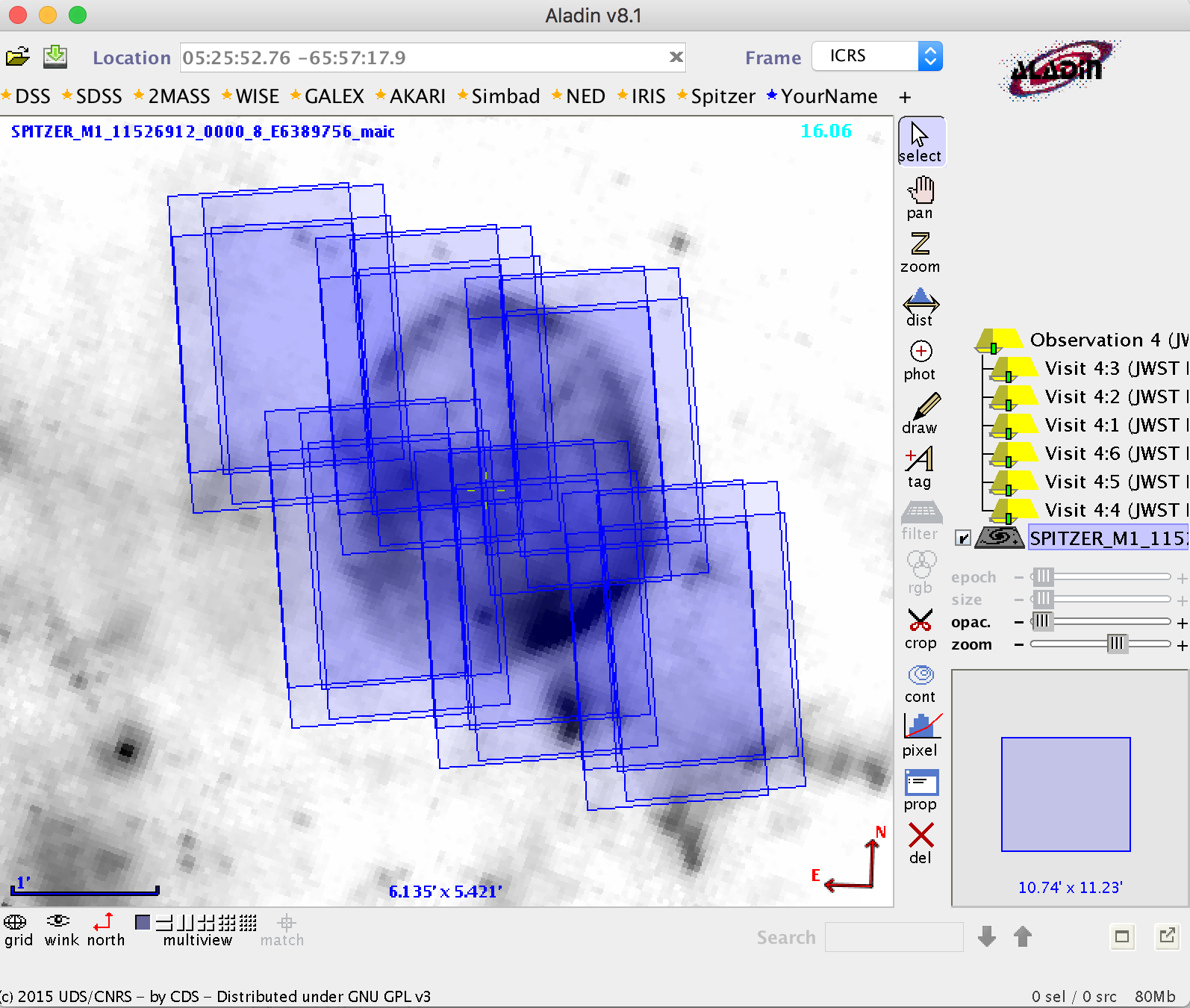
Footprint of a 2 × 3 MIRI imaging mosaic using FULL array tiles, with a 10% tile overlap and no row and/or column shifts. The footprints of the 4-Point-Sets dither pattern are evident in the figure, while the blue shading reflects the level of exposure time coverage.
The same mosaic as in Figure 1 using FULL array tiles, but with 20% overlap between tiles, and row and column shifts of 20°. The footprints of the 4-Point-Sets dither pattern are evident in the figure, while the blue shading reflects the level of exposure time coverage.
A Note on MIRI imager subarray mosaics
Words in bold are GUI menus/
panels or data software packages;
bold italics are buttons in GUI
tools or package parameters.
The MIRI imager mode offers a set of subarrays to facilitate observations of bright targets (see MIRI Detector Subarrays). Two of those subarrays, the SUB128 and SUB64, include a set of 4 reference pixels columns on the left hand side of the detector. The right hand side edge of the subarray is light sensitive, but often subarray data shows undesired features in those last columns due to the change in readout.
With th release of APT 2023.3, the default mosaic overlap is set to 20%. When building up mosaics using the SUB128 or SUB64 subarrays, the recommended % overlap should be at least 20%, or a larger percentage as deemed necessary by the observer.

