JWST ETC IFU Strategies
The JWST Exposure Time Calculator (ETC) Strategy tab for the NIRSpec IFU, MIRI MRS, and MIRI MRS time-series modes offers up to 4 different options: IFU Aperture Photometry, IFU On-Target 2-Point Nod, IFU On-Target + Off-Target Pointing, and IFU On-Target N-Point Nod.
On this page
Words in bold are GUI menus/
panels or data software packages;
bold italics are buttons in GUI
tools or package parameters.
The IFU Aperture Photometry, IFU On-Target 2-Point Nod, IFU On-Target + Off-Target Pointing, and IFU On-Target N-Point Nod strategies allow users to specify how and from where the background flux should be extracted for the signal-to-noise calculation.
The IFU On-Target N-Point Nod strategy is only available for the NIRSpec IFU calculation type. This strategy is the ETC implementation of the 4-POINT-NOD pattern, which has no equivalent for the MIRI MRS.
IFU On-Target 2-Point Nod and IFU On-Target N-Point Nod will produce a higher SNR for the same Detector Setup parameters compared with IFU On-Target + Off-Target Pointing or IFU Aperture Photometry because the source flux is being accumulated both at the initial position and at the "nod" position(s). For IFU On-Target + Off-Target Pointing, there is no source flux in the off-source nod position because it is completely off the scene and only contains the sky background. Only half of the exposure time requested for the IFU On-Target + Off-Target Pointing strategy is on-source and hence the SNR is lower. The IFU Aperture Photometry option uses only a single "pointing."
IFU Aperture Photometry
Figure 1. Layout for IFU Aperture Photometry under the Strategy tab
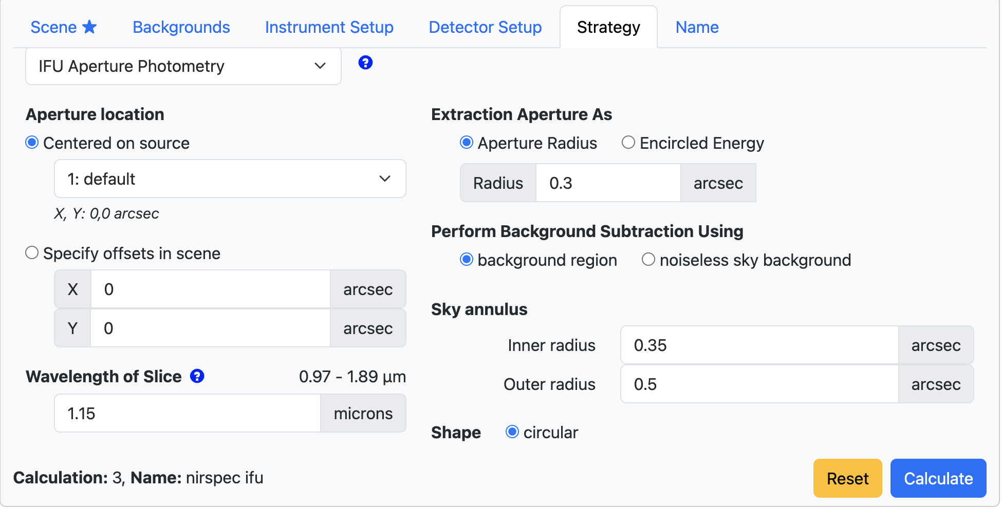
Click on the figure for a larger view.
- Aperture location can be specified to be centered on a source which can be selected from the drop-down menu, or can be specified as an X- and Y-offset from the scene center.
- Shape of the aperture for this strategy is circular with the radius measured in units of arcseconds.
- Extraction Aperture As allows for the selection of one of two options: Aperture Radius or Encircled Energy. The default is Aperture Radius, which is specified in arcseconds. Encircled Energy is specified in percentage of the flux contained within the aperture, with the aperture size for a given percentage varying with wavelength and ultimately dependent on the choice of Wavelength of Slice.
For point sources, the SNR can be highly dependent on the choice of Aperture Radius or Encircled Energy. It is recommended that users test different values to optimize the SNR in the calculation.
- Perform Background Subtraction Using: There is an option to perform background subtraction using the background estimated from a background region specified by the user, or using a noiseless sky background. The background region is defined by specifying the Inner radius and Outer radius parameters for the Sky annulus.
Note that when a Sky annulus is specified, it includes contamination from all sources within the scene that contribute to the annulus in addition to the sky, e.g., when overlapping sources are present, or extended profile wings of the source itself contributes to the background extraction aperture. When the background subtraction is performed, the contamination and sky contributions are subtracted. The estimated contamination from sources within the scene over the sky background is reported in the ETC output Reports pane as "Fraction of Total Background due to Signal from Scene."
If the option to use the noiseless sky background is selected, then the count rate corresponding to the sky background chosen in the Backgrounds tab is used for background subtraction. When the noiseless sky background is opted for background subtraction, the contamination from within the scene is not subtracted from the extracted source flux. The users may want to consider using a noiseless sky background in some cases, for example, when performing photometry of a source that is located on a bright extended background with significant gradient within the background annulus. Also, a noiseless sky background may be preferred when performing point source photometry with a constant aperture radius and doing a batch expansion over filters, to account for the larger PSF at longer wavelengths.
The Sky annulus values are always specified in units of arcseconds, regardless of whether Aperture Radius or Encircled Energy is chosen for Extraction Aperture As. - Wavelength of Slice corresponds to the wavelength at which the 2-D images are displayed in the output and the scalar values are reported in the Reports pane. A default value is provided but can be changed by the user. The allowed wavelength range depends on the choices made in the Instrument Setup tab (i.e., depending on the channel and disperser combination for the MIRI MRS or MIRI MRS time series and the Grating/Filter Pair for the NIRSpec IFU). If the Wavelength of Slice provided is invalid, the affected tab names will turn italicized in red and an explanatory red text will appear to indicate the incorrect parameter.
IFU On-Target 2-Point Nod
Figure 2. Layout for IFU On-Target 2-Point Nod under the Strategy tab

Click on the figure for a larger view.
- Aperture location can be specified to be centered on a source which can be selected from the drop-down menu, or can be specified as an X- and Y-offset from the scene center.
- Shape of the aperture for this strategy is circular with the radius measured in units of arcseconds. A default value is provided for the Aperture radius, but this can be changed by the user.
For point sources, the SNR can be highly dependent on the choice of Aperture radius. It is recommended that users test different values for the Aperture radius to optimize the SNR in the calculation.
- Nod position in scene is used for background determination from within the scene and is specified by providing the X- and Y-position in arcseconds. The second nod (the offset nod) is subtracted from the first nod (see Figure 3), then flux is extracted within the specified aperture at each position and co-added. The number of integrations, which is specified under the Detector Setup tab, is multiplied by a factor of 2 to account for both nods.
- Wavelength of Slice corresponds to the wavelength at which the 2D images are displayed in the output and the scalar values are reported in the Reports pane. A default value is provided but can be changed by the user. The allowed wavelength range depends on the choices made in the Instrument Setup tab (i.e., depending on the channel and disperser combination for the MIRI MRS or MIRI MRS time series and the Grating/Filter Pair for the NIRSpec IFU). If the Wavelength of Slice provided is invalid, the affected tab names will turn italicized in red and an explanatory red text will appear to indicate the incorrect parameter.
- Angular units is fixed as arcseconds and determines the units for the Aperture location, Aperture radius, and Nod position in scene.
Figure 3. Schematic diagram showing the IFU On-Target 2-Point Nod strategy

Position 1: Source and scene specified by user. The source may be offset from the center of the scene, but here we present a source centered in the middle of the scene.
Position 2: Nod position specified by the user under the Strategy tab. Default values are provided but can be changed.
Difference image: Position 2 subtracted from Position 1. Red in this image indicates a positive value, while blue indicates a negative value. The SNR is the co-addition of both positions.
IFU On-Target + Off-Target Pointing
Figure 4. Layout for IFU On-Target + Off-Target Pointing under the Strategy tab

Click on the figure for a larger view.
- Aperture location can be specified to be centered on a source, which can be selected from the drop-down menu, or can be specified as an X- and Y-offset from the scene center.
- Shape of the aperture for this strategy is circular with the radius measured in units of arcseconds. A default value is provided for the Aperture radius, but this can be changed by the user.
For point sources, the SNR can be highly dependent on the choice of Aperture radius. It is recommended that users test different values for the Aperture radius to optimize the SNR in the calculation.
- Wavelength of Slice corresponds to the wavelength at which the 2D images are displayed in the output and the scalar values are reported in the Reports pane. A default value is provided but can be changed by the user. The allowed wavelength range depends on the choices made in the Instrument Setup tab (i.e., depending on the channel and disperser combination for the MIRI MRS and the Grating/Filter Pair for the NIRSpec IFU). If the Wavelength of Slice provided is invalid, the affected tab names will turn italicized in red and an explanatory red text will appear to indicate the incorrect parameter.
- Angular units is fixed as arcseconds and determines the units for the Aperture location and Aperture radius.
IFU On-Target N-Point Nod (NIRSpec IFU only)
Figure 5. Layout for IFU On-Target N-Point Nod under the Strategy tab

Click on the figure for a larger view.
A fourth strategy option is available only for the NIRSpec IFU mode which allows users to mimic the 4-POINT-NOD pattern. The following are sub-options within this strategy:
- Aperture location can be specified to be centered on a source, which can be selected from the drop-down menu, or can be specified as an X- and Y-offset from the scene center.
- Shape of the aperture for this strategy is circular with the radius measured in units of arcseconds. A default value is provided for the Aperture radius, but this can be changed by the user.
For point sources, the SNR can be highly dependent on the choice of Aperture radius. It is recommended that users test different values for the Aperture radius to optimize the SNR in the calculation.
- Wavelength of Slice corresponds to the wavelength at which the 2-D images are displayed in the output and the scalar values are reported in the Reports pane. A default value is provided but can be changed by the user. The allowed wavelength range depends on the choices made in the Instrument Setup tab (i.e., depending on the channel and disperser combination for the MIRI MRS and the Grating/Filter Pair for the NIRSpec IFU). If the Wavelength of Slice provided is invalid, the affected tab names will turn italicized in red and an explanatory red text will appear to indicate the incorrect parameter.
- Angular units is fixed as arcseconds and determines the units for the Aperture location and Aperture radius.
- Dither Patterns has only one option, Default 4 Point Nod, that specifies the number of nod positions (4) and their placement on the detector.
Figure 6. Image of the IFU On-Target N-Point Nod strategy

As shown in the figure above, the IFU On-Target N-Point Nod strategy in the ETC places the target in only a single location in the scene, in this case, the bottom left quadrant. The location in the bottom left quadrant, with respect to the scene center, matches that of the true NIRSpec 4-POINT-NOD, but in order to save computation time, the target is not explicitly moved to the other 3 quadrants. Instead, this strategy in the ETC reuses the initial nod position image for all 4 nod calculations, and measures the background flux from the other 3 nod positions every time, which for perfect synthetic data still delivers results equivalent to the full 4-point nod. Thus, the image above does not match what is output by the JWST Calibration Pipeline, where negative PSF images are present in the other 3 quadrants.