JWST Near Infrared Camera
The JWST Near Infrared Camera (NIRCam) offers imaging, coronagraphy, wide field slitless spectroscopy, and time-series monitoring both in imaging and spectroscopy, as well as wavefront sensing measurements for JWST mirror alignment.
On this page
The JWST Near Infrared Camera (NIRCam) observes from 0.6 to 5.0 μm and offers imaging, coronagraphy, wide field slitless spectroscopy, and time-series monitoring both in imaging and spectroscopy. NIRCam has 2 nearly identical modules pointing to adjacent fields of view. Each module uses a dichroic to observe simultaneously in a short wavelength channel (0.6–2.3 μm) and a long wavelength channel (2.4–5.0 μm).
NIRCam has 5 observing modes for science:
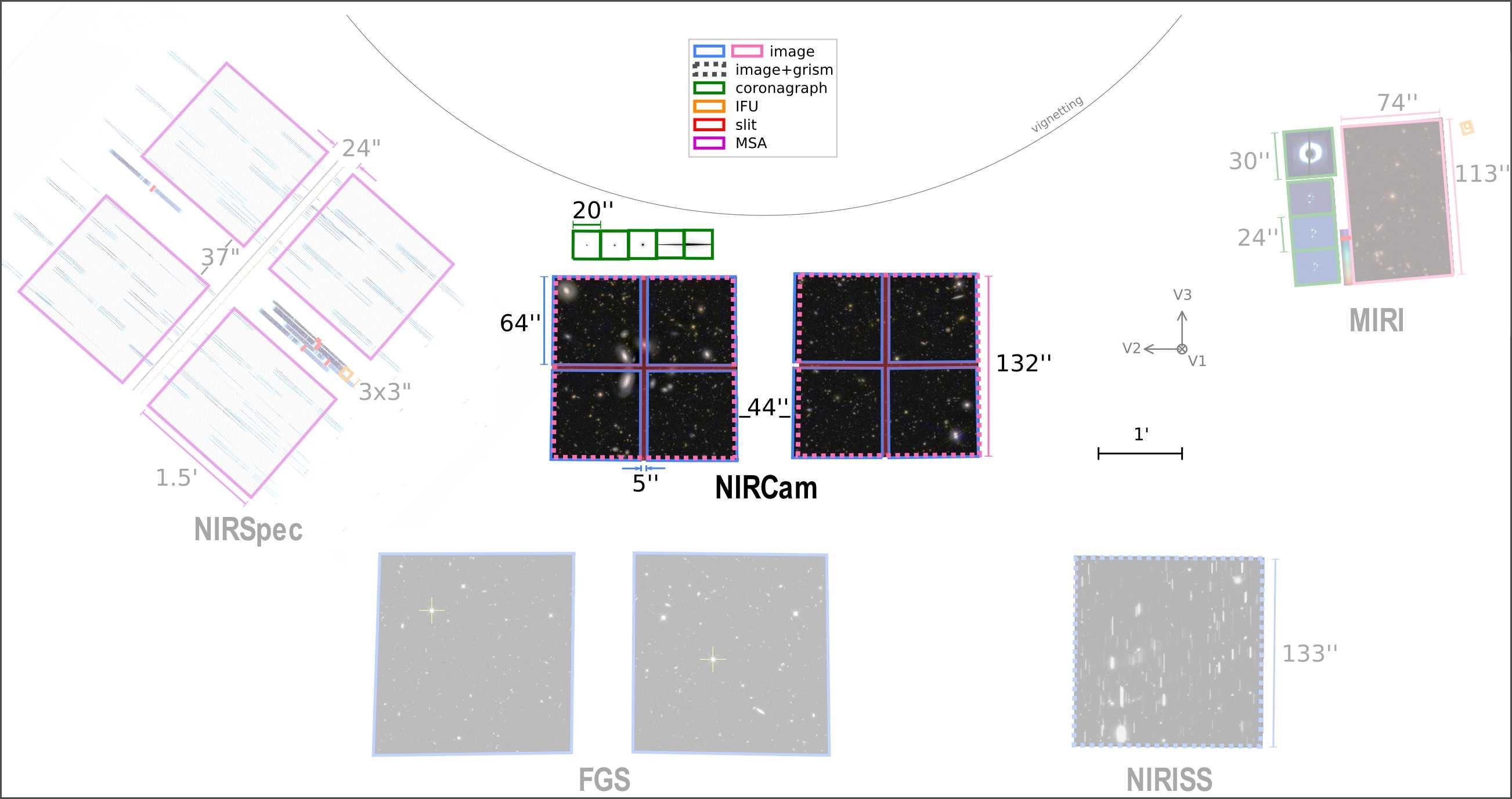
- Imaging of two 2.2' × 2.2' fields separated by a 44" gap, covering 9.7 arcmin² in total with a set of 29 filters
- Coronagraphic imaging at multiple wavelengths
- Wide field slitless spectroscopy (2.4–5.0 µm) using grisms with resolving power R = λ/Δλ ~ 1,600 at 4 µm
- Time-series imaging (photometric monitoring)
- Grism time series (spectroscopic monitoring) again using grisms with resolving power R = λ/Δλ ~ 1,600 at 4 µm
NIRCam can also perform wavefront sensing measurements to align and phase JWST's primary mirror.
Observational capabilities
Each observing mode offers distinct capabilities and uses a subset of the optical elements available in the pupil and filter wheels.
Table 1. NIRCam observing mode parameters
Observing mode | Wavelength | Field of view§ | Pixel | Notes |
|---|---|---|---|---|
| 0.6–2.3 | 2 × 132" × 132" | 0.031 | FWHM 2 pix at 2.0 µm | |
| 2.4–5.0 | 2 × 129" × 129" | 0.063 | FWHM 2 pix at 4.0 µm | |
1.8–2.2 | 20" × 20" | 0.031 0.063 | ||
| Wide field slitless spectroscopy | 2.4–5.0 | 2 × 129" × 129" | 0.063 | R ~ 1,600 at 4 µm |
| Time-series imaging | 0.6–2.3 2.4–5.0 | 129" × 129" | 0.031 0.063 | |
| Grism time series | 2.4–5.0 | 129" × 129" | 0.063 | R ~ 1,600 at 4 µm |
§ Smaller fields of view are available using subarrays in the imaging, time series imaging, and grism time-series modes.
Field of view
Modules
NIRCam consists of 2 redundant modules—A and B—with identical optical elements and nearly identical throughput. The NIRCam observing modes include options to use either a single module or both simultaneously with identical integration times, readout patterns, and filters.
Channels
Each module includes a short (0.6–2.3 µm) and long (2.4–5.0 µm) wavelength channel. NIRCam uses a dichroic to observe at both wavelengths simultaneously in roughly the same field of view.
Table 2. Properties of short and long wavelength channels
| Short wavelength channels | Long wavelength channels | |
|---|---|---|
Wavelength range | 0.6–2.3 μm | 2.4–5.0 μm |
Fields of view | 2 × 2.2' × 2.2' (with 4"–5” gaps) | 2 × 2.2' × 2.2' |
Pixels† | 8 × 2040 × 2040 pixels | 2 × 2040 × 2040 pixels |
Nominal pixel scale | 0.031"/pixel | 0.063″/pixel |
PSF FWHM‡ | 0.064" @ 2μm (Nyquist) | 0.13" @ 4 μm (Nyquist) |
Grism slitless spectroscopy | N/A | R ~ 1600 at 4 μm |
round: 2.1 μm bar: 1.8–2.2 μm | round: 3.35, 4.3 μm bar: 2.5–5.0 μm |
† Not including reference pixels insensitive to light that are 4 pixels along each outer edge.
‡ PSF undersampled at lower wavelengths; slightly broader for coronagraphy.
Optical elements
Each channel includes a pupil wheel and a filter wheel, each with 12 optical elements, which may be used in various combinations. These elements include:
Filters with extra-wide, wide, medium and narrow passbands;
Coronagraphic Lyot stops to suppress light that passes the occulting masks;
Grism elements for slitless spectroscopy in the long wavelength channel;
Weak lenses to defocus light from bright sources to avoid detector saturation, also used for telescope alignment.
Within each module, light may (optionally) be passed through a coronagraphic occulting mask in the focal plane before being divided by the dichroic beam splitter to the short and long wavelength channels.
Filters
The 29 NIRCam filters have names "Fnnnx" where "nnn" refers to the central wavelength (e.g., 220 for 2.20 µm) and "x" refers to the filter width: "W2" for extra-wide (R ~ 1), "W" for wide (R ~ 4), "M" for medium (R ~ 10) and "N" for narrowband (R ~ 100).
Detectors
NIRCam has 10 Teledyne HgCdTe H2RG detectors, or sensor chip assemblies (SCAs), each with 2040 × 2040 pixels sensitive to light. Eight short wavelength detectors cover roughly the same area on the sky as the 2 long-wavelength detectors. In full frame imaging mode, all 10 detectors are read out non-destructively every 10.74 s. The smallest supported science subarray (64 × 64 pixels) can be read out in 49 ms (the shortest exposure time).
Sensitivity
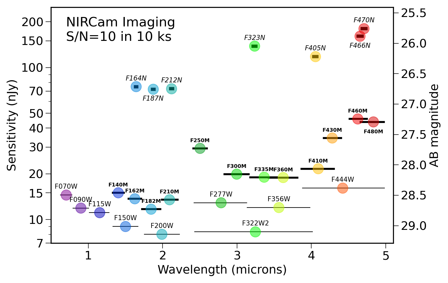
In a 10 ks image, NIRCam reaches S/N ~ 10 on point sources as faint as ~10 nJy (AB mag 28.9) in some wide filters. See NIRCam Imaging Sensitivity.
Please use the Exposure Time Calculator (ETC) for the most up-to-date sensitivity estimates for specific proposed observations. See the NIRCam Sensitivity article for more information.
Saturation
In standard imaging mode NIRCam bright source saturation limits range between ~9 and ~16 Vega magnitudes, depending on the filter. Subarrays allow for shorter readout times to reach brighter magnitudes. Brighter magnitudes can also be reached in the time-series observing modes, as weak lenses (at short wavelengths) and grisms (at long wavelengths) spread the bright light over more detector pixels. Stars observable without saturation (80% full well) include those visible to the unaided eye: ~5th magnitude or brighter, depending on the observing mode, wavelength, and configuration.
Please use the ETC to calculate saturation estimates for your proposed observations.
Data calibration and analysis
Information about calibration is available in the JWST Science Data Overview article. This article and its links point to content about absolute astrometric, flux, and wavelength calibration, as well as information on calibration reference files.
Details about the structure and format of the data can be found in the Understanding JWST Data Files article. The JWST calibration pipeline is described in both the JWST Science Calibration Pipeline article and the official software documentation. More information about post-pipeline processing can be found in the JWST Post-Pipeline Data Analysis article.
External NIRCam links and documents
University of Arizona NIRCam website
Lectures
JWST Community Lecture Series - NIRCam: Your Next Near-Infrared Camera (M. Rieke)
Acknowledgements
NIRCam was built by a team at the University of Arizona (UofA) and Lockheed Martin's Advanced Technology Center, led by Prof. Marcia Rieke at UoA.
References
Rieke, M. et al. 2005, SPIE, 5904, 1
Overview of James Webb Space Telescope and NIRCam's Role
Rieke, M. et al. 2003, SPIE, 4850, 478
NGST NIRCam Scientific Program and Design Concept
Beichman, C. et al. 2012, SPIE, 8442, 2
Science opportunities with the near-IR camera (NIRCam) on the James Webb Space Telescope (JWST)
NIRCam Papers from the August 2005 SPIE meeting


