JWST Observatory Coordinate System and Field of Regard

The JWST Observatory, as a whole, has a reference coordinate system used by operations to define the pointing of the telescope within the field of regard (FOR), including defining the continuous viewing zone (CVZ) available to the observatory.

On this page

See also: Target Viewing ConstraintsJWST Position Angles, Ranges, and Offsets 

The JWST Observatory V1, V2, V3 coordinate system is primarily used in operations, but there are a number of instances where users may want to understand the orientation of the focal plane or one of the science instruments in the context of the observatory's pointing. Also, there are a number of places, for example, in various APT diagnostic plots, where the V axes are used to provide an instrument-independent reference frame.

This article provides information to link the V axes definitions to other JWST software and systems. Furthermore, the JWST field of regard (FOR) defines the instantaneous region of the sky that is available for safe JWST pointing of the telescope boresight (the V1 axis).


JWST field of regard (FOR)

  STScI Office of Public Outreach video on JWST Field of Regard

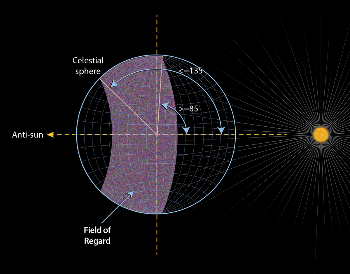
The JWST field of regard (FOR) is the region of the sky where scientific observations can be conducted safely at a given time. The FOR is defined by the allowed range of boresight pointing angles for the observatory relative to the sun line, which must remain in the range 85° to 135° at all times to keep the telescope behind the sun shield. Thus, the FOR is a large torus on the sky that moves roughly 1° per day in ecliptic longitude, following the telescope in its path around the sun. Over time, this annulus sweeps over the entire celestial sphere. As a result of the FOR, JWST can observe about 39% of the full sky on any given day and can access 100% of the sky over 6 months. Figure 1 shows a schematic of the FOR.

Figure 1. The JWST field of regard

The JWST field of regard extends from a solar elongation of 85° to 135° and changes over time as the observatory orbits the sun. (Adapted from: JWST Mission Operations Concept Document, Figure 4.10.)

Beginning in late 2022, NASA has imposed a micrometeoroid avoidance zone to minimize potential impacts from space debris coming from the direction of orbital motion.  This zone overlaps a significant portion of the orbital leading side of the FOR torus.  Observations in this overlap region with the FOR are not disallowed, but must be minimized for the long term safety of the observatory. Starting with Cycle 2, APT contains warnings and errors related to proposed observations that require observations in this restricted region.


JWST Observatory coordinate system

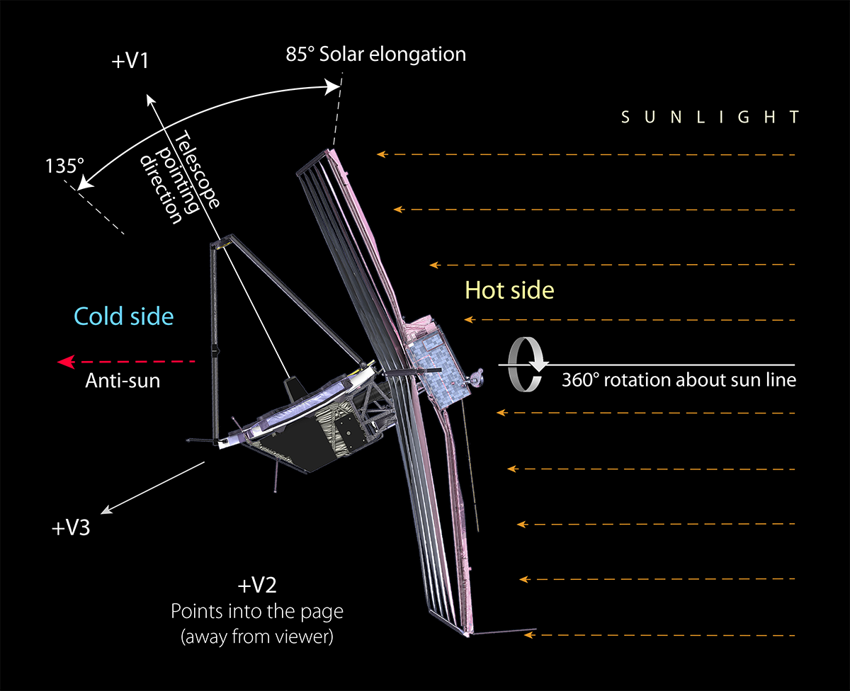
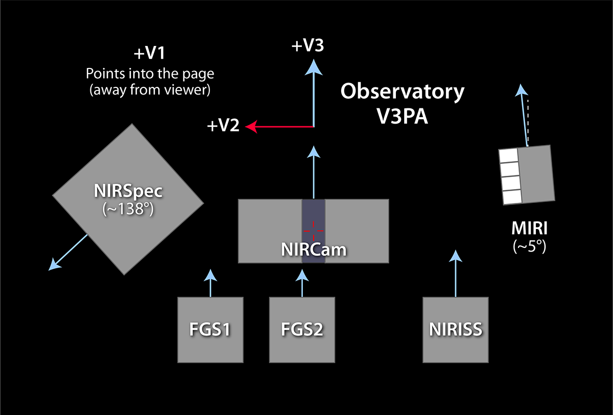
The observatory V axes are defined with respect to the telescope, as shown in Figure 2. +V1 is the boresight of the telescope, +V3 points away from the sun shield, and +V2 is orthogonal to both of these, forming the "thumb" of a right-handed coordinate system. In the context of Figure 2, the V2 axis is pointing towards the reader (out of the screen). The +V3 axis projection onto the sky, referenced eastward from north, is used within the APT diagnostics (for example in the Visit Planner) as an instrument-independent reference frame.

Figure 2. Schematic of the JWST V1, V2, V3 coordinate system

This schematic shows the JWST Observatory coordinate definitions. The sun shines from below in this figure, and the V2 axis points out of the screen toward the reader.
In Figure 3, the JWST coordinate system is shown in the context of the FOR. If the observatory is pointed at 90° solar elongation, the +V3 axis points toward the anti-sun, but as the boresight points elsewhere in the FOR, V3 moves away from the anti-sun direction. In the view shown in Figure 3, the +V2 axis is pointing into the screen.
Figure 3. The JWST Observatory coordinates in the context of the field of regard

This figure shows the JWST Observatory coordinates where V2 points into the screen. Note that the observatory can rotate around the sun line and stay within the field of regard.
Figure 4 shows another view to highlight the restrictions on instantaneous roll about the boresight (+V1 axis). The amount the observatory can roll about the V1 axis is very limited due to the requirement to keep the telescope completely behind the sun shield at all times. The ±5° value shown in the figure is only approximate as the amount of off-axis roll allowed is actually a function of the V1 solar elongation (ranging from approximately ±3° to ±7° as V1 moves from 85° to 135° solar elongation). The limitation on roll comes into play for the so-called "roll dithers" used in many coronagraphic programs. (See the JWST Dithering Overview article for more information.)
Figure 4. The JWST Observatory coordinates in the context of the roll angle

This figure shows the JWST Observatory coordinates in context of the roll angle. V1 points toward the reader (out of the screen). Note that the sunlight comes from the bottom of this figure, and the ±5° shown is only approximate.
Figure 5 shows the connection between the V axes and the JWST focal plane. The V3 axis is the primary observatory reference axis used in APT and in operations to connect the individual instrument reference axes (blue arrows) in the planning and scheduling system to the celestial sphere. This is especially important for any observations where the positioning of the instrument fields of view on the sky is important. See the JWST Position Angles, Ranges, and Offsets article for more information.  This figure can also help users understand the output from the JWST Target Visibility Tools, which typically report both  V3PA and individual instrument reference position angles.  Note that NIRCam and NIRISS are very nearly aligned with V3PA, while MIRI is offset slightly.  Only the NIRSpec reference axis is offset by a large amount relative to V3PA.

Figure 5. The JWST Observatory coordinates in the context of the focal plane
This figure shows the JWST Observatory coordinates in the context of the focal plane. The +V1 (boresight) points into the screen. The blue arrows indicate the reference axes of the individual instruments and the observatory V3 position angle is shown at the top..

Continuous viewing zone (CVZ)

Because JWST operates in an ecliptic coordinate framework, there are 2 small continuous viewing zones (CVZs) centered at each of the ecliptic poles (see Figure 6). The 85° solar exclusion zone then determines the radius of the allowed CVZs to be essentially 5°, although any observation approaching the 85° limit will have additional limitations due to safety considerations.

Figure 6. An all-sky map showing the location of the CVZs relative to galactic extinction
Magenta lines show the ecliptic plane (b = 0°) and latitudes b = ±30°, ±60°, and ±85° vs. equatorial coordinates (RA and Dec). The b = ±85° ovals enclose the JWST CVZs, the areas within 5° of the ecliptic poles (b = ±90°). The background color map shows Galactic extinction measured by Schlegel, Finkbeiner, and Davis (1998). Note the higher extinction and SMC visible within the southern CVZ.

In standard J2000 equatorial coordinates, the CVZs are centered at the following coordinates:

N-CVZ: 18h00m00.00000s  +66°33'38.5520" (or 270.00000000°  +66.56070889°)  

S-CVZ: 6h00m00.00000s  −66°33'38.5520" (or 90.00000000°  −66.56070889°)

The S-CVZ encompasses a portion of the Large Magellanic Cloud.


References

Schlegel, D. J., Finkbeiner, D. P., Davis, M. 1998, ApJ, 500, 525
Maps of Dust Infrared Emission for Use in Estimation of Reddening and Cosmic Microwave Background Radiation Foregrounds


Latest updates
  •   
    Added a note about the micrometeoroid avoidance zone

  •   
    Added video link at top of article.


  • Updated with additional links for 2020 Cycle 1.

  •  
    Added Figure 6 to CVZ definition


  •  
    Added short section on CVZ definition
Originally published