JWST Imaging
Several JWST instruments have imaging capabilities, covering different fields of view and wavelengths.
On this page
Standard imaging overview
See also: JWST Imaging Roadmap, MIRI Imaging, NIRCam Imaging, NIRISS Imaging, JWST Mosaic Overview, JWST Dithering Overview
MIRI, NIRCam, and NIRISS are the imaging instruments on JWST. The wavelength ranges and available modes of use are summarized in Table 1. The articles MIRI Imaging, NIRCam Imaging, and NIRISS Imaging provide details for each instrument. Figure 1 shows the relative positions of these imaging fields of view in the JWST focal plane.
In addition, an JWST Imaging Roadmap article is available for planning imaging observations. If you plan to use imaging in coordinated parallel mode, see the JWST Coordinated Parallels Roadmap.
Figure 1. Imager fields of view in the JWST focal plane

The 3 imaging instruments (NIRCam, NIRISS, and MIRI) are highlighted here in the JWST focal plane. FGS indicates the Fine Guidance Sensor fields of view, used for guiding.
Table 1. Summary of JWST's standard imaging capabilities
| Instrument | Wavelength range | Mode of use |
|---|---|---|
| NIRCam | 0.6 μm < λ < 5 μm | Primary or parallel |
| MIRI | 5.6 μm < λ < 25.5 μm | Primary or parallel |
| NIRISS | 0.8 μm < λ < 5 μm | Primary or parallel |
For convenience, Figure 2 provides a visual representation of the relative wavelength coverage. JWST time-series observations (TSO) and high-contrast imaging (HCI) also use the imagers and are shown for completeness. However, they involve specialized operations that are described elsewhere in JDox.
Figure 2. Summary of JWST's imaging capabilitities

Wavelength coverage of each instrument, highlighting different imaging capabilities.
NIRCam provides imaging in 2 wavelength ranges simultaneously over the same 9.7 arcmin² field of view (via a dichroic): 0.6–2.3 μm (0.031"/pix) and 2.4–5.0 μm (0.063"/pix). It uses 2 near-identical side-by-side modules, separated by a 44" gap. Within each module, NIRCam's short wavelength channel also has small 4"–5" gaps between detectors.
MIRI offers imaging at a complementary wavelength range, from 5.6 to 25.5 μm over a 74" × 113" field of view, and has a detector plate scale of 0.11"/pixel.
NIRISS offers 0.8–5.0 μm (0.066"/pixel) imaging in a 4.84 arcmin² field of view and many of its filters are essentially identical counterparts to the NIRCam filters. Consequently, NIRCam and NIRISS can be used in parallel to increase the sky coverage at a particular wavelength.
All the standard imaging modes offer a mosaicking capability for observing larger areas. Dithering is also recommended for imaging to improve data quality, and is required for NIRISS imaging observations when NIRISS imaging is a prime observing mode.
Imaging spatial resolution
Details about the point spread function (PSF) FWHMs for each instrument are summarized in Table 2. More information is available in these articles:
Table 2. Information on imaging spatial resolution
PSF FWHM | Plate scale | Nyquist sampled | |
|---|---|---|---|
| NIRCam | 0.935–2.323 (SW) 1.349–2.603 (LW) | 0.031"/pix (SW) 0.063"/pix (LW) | >2 μm (SW) >4 μm (LW) |
| NIRISS | 1.33 - 2.54 | 0.066"/pixel | F380M filter and longer wavelength filters are Nyquist sampled |
| MIRI | 1.6–7.45 | 0.11"/pix | >6.25 μm |
Imaging sensitivities
See also: NIRCam Imaging Sensitivity, NIRISS Sensitivity, MIRI Sensitivity, NIRCam Detector Readout Patterns, MIRI Detector Readout Overview, NIRISS Detector Readout Patterns, JWST ETC
The sensitivity of each JWST imaging filter is summarized in Figure 3. The JWST Exposure Time Calculator (ETC) was used to estimate the signal to noise (S/N), with readout patterns chosen to reach approximately 10 ks in each instrument and using a benchmark background, as described in the JWST Background Model article. Also, consider using the JWST Interactive Sensitivity Tool to explore the relevant parameter space for the various imagers.
Figure 3. JWST imaging sensitivity
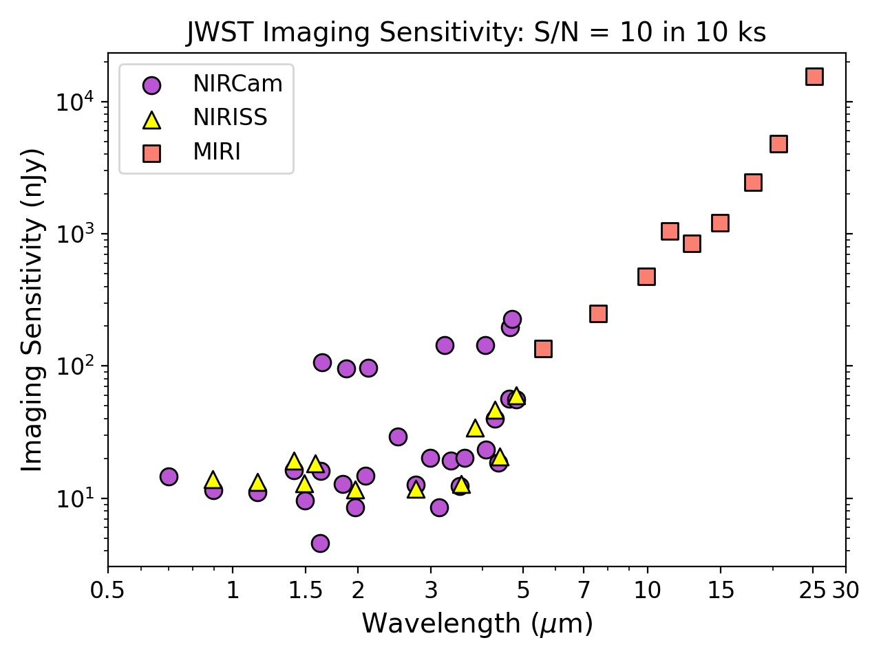
The S/N = 10 detection limits of JWST's imaging instruments in 10 ks, shown for every available filter. Sources are assumed to have a flat spectrum in nJy and a benchmark background, as described on the JWST Background Model article. Please use the JWST Exposure Time Calculator (ETC) to calculate sensitivity estimates for your specific proposed observations. Plot created using ETC 5.0.