NIRCam 1/f Noise Removal Methods
Various methods have been developed to mitigate 1/f detector noise that appears as stripes in JWST data. None has yet been implemented in the JWST calibration pipeline for NIRCam since detailed testing of these methods is still in progress, with several of these methods being available publicly. This article covers these methods on NIRCam data for various scenes, both sparse and crowded.
On this page
JWST SIDECAR ASICs (detector readout electronics) generate significant 1/f noise during detector operations and signal digitization. This 1/f noise appears as horizontal or vertical banding that spans the entire width of the image, and vary from row to row or column to column depending on the employed read-out direction of all NIR JWST instruments. If not handled properly, it can cause one to overlook faint targets, or over-estimate the statistical significance of a detection on imaging data and introduce systematic errors in time-series observations. More discussion of 1/f noise is provided in NIRCam Detector Performance and NIRCam Known Issues.
The reference pixel correction step of the stage 1 pipeline can partly mitigate 1/f noise. But, with the limited number of reference pixels available in NIRCam (and other JWST instruments) observations (four pixels on each edge of the full array images), the 1/f noise cannot be completely removed. 1/f correction is expected to be even less effective in subarray observations, which typically contain no or few reference pixels.

Click on the figure for a larger view.
Demonstration of 1/f noise by blinking an uncorrected and corrected NIRCam image. The 1/f noise becomes evident as horizontal striping across the full detector.
1/f software packages
Words in bold are GUI menus/
panels or data software packages;
bold italics are buttons in GUI
tools or package parameters.
All methods are described in more detail below in Section 5. Note that NSClean will be implemented in the JWST pipeline for NIRSpec data.
Table 1. 1/f-noise mitigation packages developed in Python for JWST imaging data
"Columns" and "Rows" refer to the fast and slow readout directions, respectively, though these directions may be swapped for different observing modes or instruments.
| Package name | Developer | Rows (slow) | Columns (fast) | Full Rows | Individual Amplifiers | Retains Background | Source | Notes |
|---|---|---|---|---|---|---|---|---|
| image1overf | Chris Willott | X | X | X | X | optional | Computes background image and employs it to remove row median levels | |
| remstriping | Micaela Bagley | X | X | X | X | optional | Removes column and row medians from NIRCam rate or calibrated images | |
| NSClean | Bernie Rauscher | X | X | X | user provided | Originally developed for NIRSpec MSA observations including many blank unilluminated pixels to precisely measure and subtract background Fourier modes | ||
| ROEBA | Everett Schlawin | X | X | X | X | user provided | Developed for NIRCam TSO weak lens NIRCam observations. Requires user-provided background image to remove column odd/even and row median levels. | |
| smooth1overf | Dan Coe | X | X | X | X | Simple smoothing of sigma-clipped medians for rows and columns | ||
| destriper | Massimo Roberto | X | X | X | Remove median level per amplifier by employing the full rows |
Data
The JWST NIRCam imaging mode is employed for a wide range of astronomical scenes, including sparse extragalactic fields, dense star clusters, and extended sources, such as diffuse and planetary nebulae. A representative set of public data is considered for various types of scenes, as summarized in Table 2 and Figure 2. All images have been calibrated using the STScI pipeline and obtained from the MAST archive. The pipeline processing includes the 1/f correction step using reference pixels; these are insufficient, leaving significant striping visible in the images.
Table 2. Data employed in our comparative analysis
| Program identifier | Image identifier | Field type | Scene type |
|---|---|---|---|
| 1345 | jw01345001001_10201_00001_nrca3_cal.fits | Sparse | Extragalactic "blank" field |
| 1074 | jw01074001001_02101_00001_nrca1_cal.fits | Crowded | Star field |
| 1334 | jw01334001001_02101_00001_nrca1_cal.fits | Crowded | Dense star field |
| 2107 | jw02107025001_02101_00001_nrcb2_cal.fits | Extended 1 | Galaxy close-up |
| 2731 | jw02731001001_02101_00004_nrca1_cal.fits | Extended 2 | Nebula |

Results
All packages were run on the same data set to generate 1/f corrected images. Sources were detected and masked for codes allowing that option. All results are shown below on linear scales, clipped to the same flux levels.
It must be emphasized that most methods were not designed for these general cases. Some assume sparse scenes with "blank" data regions available to measure the 1/f noise. In these cases, all of the methods perform reasonably well. When the image is more crowded or full, most methods do not perform well, oversubtracting the background and/or introducing discontinuities. This can impact the accuracy of absolute flux measurements.
The parameters of some of the packages can be optimized depending on the scene to be corrected. An exhaustive exploration of all options for improving the parameters is beyond the scope of this article.
Package versions may change owing to method improvements and bug fixes. To avoid version mismatch issues, each of the Jupyter Notebooks linked to this article also provide working versions of the 1/f noise mitigation packages employed for this analysis. It is left at the discretion to each user to adjust the latest up-to-date package version and identify potential differences from the results presented here.
Chris Willott's image1overf
This method performs well for all scenes tested, including preserving the overall flux levels without oversubtracting "background". The individual amplifier option works well on the sparse fields but introduces slight artifacts in the full fields. The code can also be run without source masking; the results are nearly identical to those with it.


Click on the figure for a larger view.
1/f noise was removed from the images above using image1overf for two options: full rows (top) and individual amplifiers (bottom).
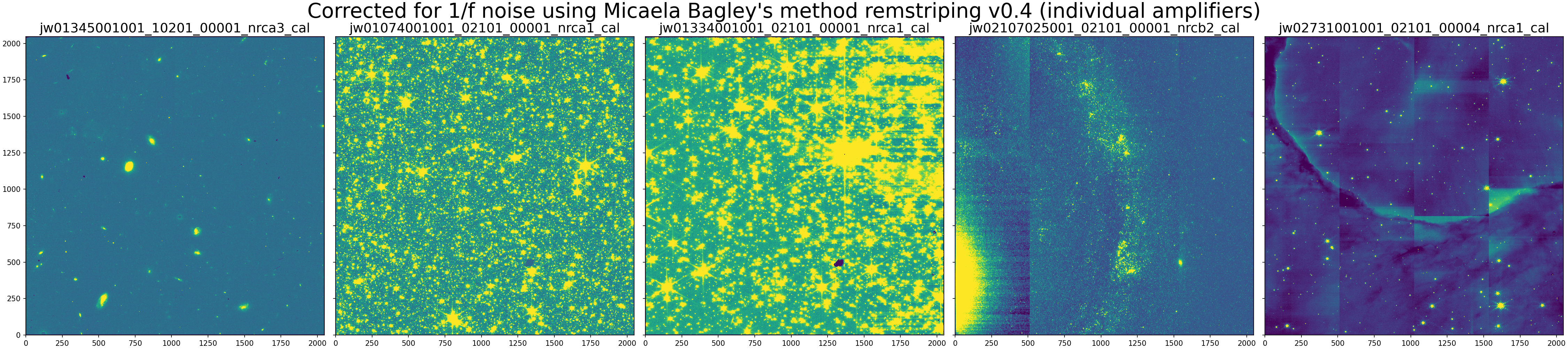
Micaela Bagley's remstriping
The example uses v0.4 available here, which fixes a few bugs. Originally developed for the CEERS program, this method performs well on the image from that dataset as well as the sparse star field. Since it measures and subtracts the 2-D background, fuller fields are left oversubtracted. Artifacts are introduced when correcting amplifiers individually.

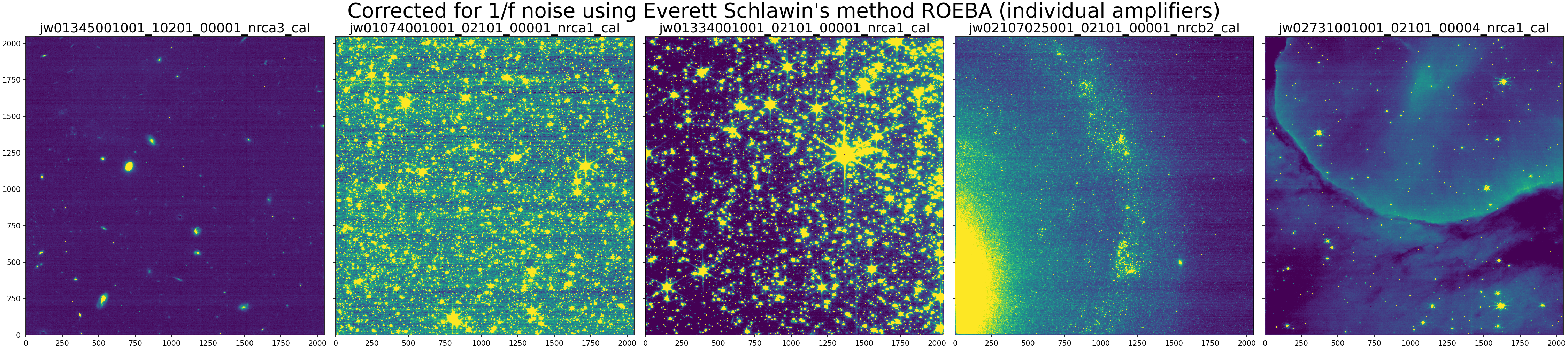
Everett Schlawin's ROEBA
Using the default parameters, this method oversubtracts background while leaving some faint striping.
Click on the figure for a larger view.
1/f noise was removed from the images above using ROEBA for individual amplifiers.
Dan Coe's smooth1overf
Designed to simply smooth the row and column medians, this method performs well in the general case, while leaving some residual striping, especially on larger scales (more than a few rows).

Click on the figure for a larger view.
1/f noise was removed from the images above using smooth1overf.
Massimo Robberto's destriper
Another simple method, this median smoothing works well on sparse fields. By processing amplifiers individually, artifacts are introduced in more full scenes.

Click on the figure for a larger view.
1/f noise was removed from the images above using destriper.
Detailed description of each method
Each of the 1/f noise mitigation packages reviewed in this article remove median image background. The packages also share the assumption for a negligible variation of the 1/f noise between two neighbor amplifiers, and a sufficient background region without scattered light or faint background point sources. The following test results include also imaging fields of extended sources as well as crowded star fields with the goal to demonstrate the performance of the individual packages including beyond their assumptions.
Chris Willott's image1overf
Example Jupyter notebook for running image1overf: from Chris Willott, or from STScI
General description and assumptions
Performs a removal of 1/f readout noise on NIRISS or NIRCam level 2 calibrated image by masking objects and subtracting the median of each column. The correction method assumes that there isn't a significant variation in the background across the field. The code has been designed to handle 1/f stripes either assuming a constant noise along the full detector rows, or amplifier-to-amplifier 1/f noise differences. Detector orientation is determined automatically by searching for the value of the header keyword SLOWAXIS. Only two subarrays are supported: FULL (NIRCam and NIRISS) and SUB256 (NIRISS) subarrays. It includes the effect of a variable background (by temporarily removing it before determining the 1/f correction and adding it back afterwards) and masking pixels containing sources. The author emphasizes that the code should be used with care and the users need to inspect the results for any unintended consequences.
Difference compared to all other packages
By temporarily subtracting a 2-D background to measure and subtract stripes, the pedestal flux level of the image is preserved, which is especially helpful for crowded scenes.
Method steps
- Subarray type is determined and non-reference pixels are extracted
- Mask bad pixels, determined from the DQ array
- Mask all pixels outside ±3-sigma of global median (adjustable with sigma_bgmask parameter)
- assumes 1/f noise variations are within this 3-sigma; also assumes background doesn't vary significantly across the field
- Temporarily subtract 2-D background grid measured using photutils
- Mask additional pixels one of two ways:
- Detect sources using photutils
- Mask all pixels outside ±2-sigma of global median of background-subtracted image (adjustable with sigma_1fmask parameter)
- Measure row stripes: medians of remaining unmasked pixels
- Perform within each amplifier individually (ABCD) or across full rows (controlled by splitamps parameter)
- Only dominant stripes are corrected, usually rows (sometimes columns) depending on which detector axis is read out slowest (determined from FITS header keyword
SLOWAXIS)
- Subtract row stripes from data (without background subtraction)
Source code and documentation
Micaela Bagley's remstriping
Example Jupyter Notebook for running remstriping: from STScI
General description and assumptions
Designed for sparse extragalactic "blank" fields observed by programs like CEERS, remstriping measures both row and column striping
For DR0.5, each 1/f noise-subtracted image was visually inspected and the masking threshold adjusted for the images with over- or under-subtracted pattern noise. For example, images with large, bright sources usually benefit from a threshold closer to 0.1 than 0.8. The threshold can either be changed using the global variable MASKTHRESH, or by setting a value manually for each image.
Originally designed to be run on "rate.fits" files, remstriping includes a step to perform flat fielding before 1/f measurement and correction. The remstriping algorithm can also be run on "cal.fits" files by turning off the flat fielding step.
Method steps
- Apply flat field (optional, assuming running on "rate" files)
- Mask sources detected using photutils 1.5 (available option to load source mask)
- Subtract median (single value, either simple median or mean of Gaussian fit)
- Measure row and column striping: sigma-clipped median of all unmasked pixels
- Measure within each amplifier individually (ABCD) and also across full rows
- Use individual amplifier measurements, unless most of the pixels are masked, then revert to the full row/column measurements
- Controlled by threshold parameter thresh: default requires 80% of pixels to be good (unmasked and free of detected sources)
- Subtract stripes from data (including background subtraction, without flat field correction)
Source code and documentation
Everett Schlawin's ROEBA
Example Jupyter Notebook for running ROEBA: from STScI
General description and assumptions
ROEBA stands for Row-by-row, Odd/Even By Amplifier correction and is part of the standalone package for reduction of transiting exoplanet data called tshirt. ROEBA has been developed for removal of 1/f noise in the SW channel of NIRCam TSOs (which can differ significantly compared to imaging fields, Schlawin et al. 2021, 2023). Such scenes typically consist of a bright source, whose PSF is defocused using one of the NIRCam SW weak lenses, and usually dominates the scene (in non-crowded fields) with a free of bright sources field providing plenty of background. In order to run ROEBA's correction, the user needs to provide a background region to employ as a proxy for reference pixels that have minimal contamination from bright sources. The package relies on the assumption for a clean background region and could potentially over-subtract light or background sources where this condition is not met.
Difference compared to all other packages
Requires user-provided background mask. Corrects for odd/even effect and uses row medians from each amplifier, or full row to correct for 1/f noise.
Method steps
- By employing a user-provided background image, ROEBA applies correction in the slow-read-out direction, which subtracts the median odd count level from all odd-numbered columns and the median count level from all even-numbered columns; this first step removes the pre-amplifier offsets;
- Calculates row-by-row median levels from the background region and subtracts this from all pixels in the given row; this reduces the 1/f noise
- controlled by amplifiers parameter
Source code and documentation
Massimo Robberto's destriper
Example Jupyter Notebook for running destriper: from Robberto, from STScI
General description and assumptions
The destriper package takes as input calibrated or "rate" NIRCam images, and corrects for 1/f noise per amplifier by removing the median level of each row. There is no assumption for the user to provide background regions for determining the median for each row.
Difference compared to all other packages
Relies on median level of amplifier image rows without source masking.
Method steps (per individual NIRCam amplifier)
- Extract image area without the reference pixels from the science extension
- Compute median level for each row
- Subtract the median for each row and offset to the median of the input data
- Subtract median for each amplifier and offset to the median level of the first amplifier
Source code and documentation
- Jupyter Notebook: Robberto's destriper code
Bernie Rauscher's NSClean
Originally developed for NIRSpec MSA observations including many blank unilluminated pixels to precisely measure and subtract background Fourier modes, using a robust theoretical basis. It can also be applied to NIRCam images of individual objects (coronagraphy or TSO) surrounded by many "blank" pixels. It was not designed for the scenes tested above, containing many objects. In those cases, additional Fourier modes are detected, measured, and subtracted, leaving artifacts, even in "blank" fields.
Work is underway to implement NSClean in the JWST pipeline for NIRSpec data.
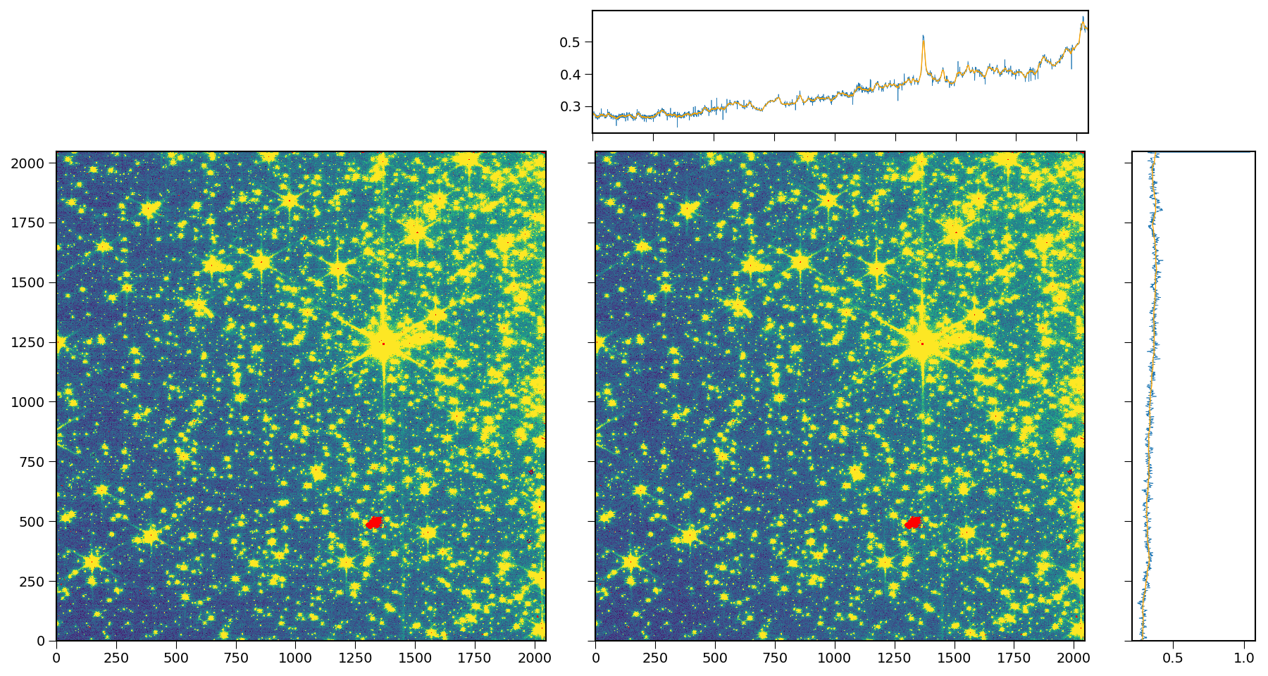
Dan Coe's smooth1overf
This simple method calculates sigma-clipped medians of each row / column, then smooths them with simple rolling averages. Shown below are the original (left) and corrected (right) images along with the sigma-clipped medians of columns (top) and rows (right) in blue, and the smoothed medians in orange used to correct the images.


Click on the figures for a larger view.
Above are the original (left) and corrected (right) images along with the sigma-clipped medians of columns and rows in blue, and the smoothed medians in orange used to correct the images.
Future work
Additional work is required to test methods against more datasets and perform quantitative analysis before considering implementation in the JWST pipeline.
Additional development of methods and code is also underway by various groups. For example, 1/f noise is present in every detector read and should be subtracted from individual reads in the "uncal.fits" files before (or as part of) ramp fitting to generate the rate.fits files.
References
Schlawin, E., et al. 2021, AJ, 161, 115
JWST Noise Floor. II. Systematic Error Sources in JWST NIRCam Time Series
Schlawin, E., et al. 2023, PASP, 135, 8001
JWST NIRCam Defocused Imaging: Photometric Stability Performance and How It Can Sense Mirror Tilts