JWST ETC Defining a New Source
The JWST Exposure Time Calculator (ETC) uses a library of sources included in astronomical scenes for ETC calculations. The sources are described by parameters that characterize their brightness, spectral properties, and shape.
On this page
Video Tutorials: ETC Scenes and Sources, Adding Emission Lines in the ETC
Words in bold are GUI menus/
panels or data software packages;
bold italics are buttons in GUI
tools or package parameters.
Create a new source
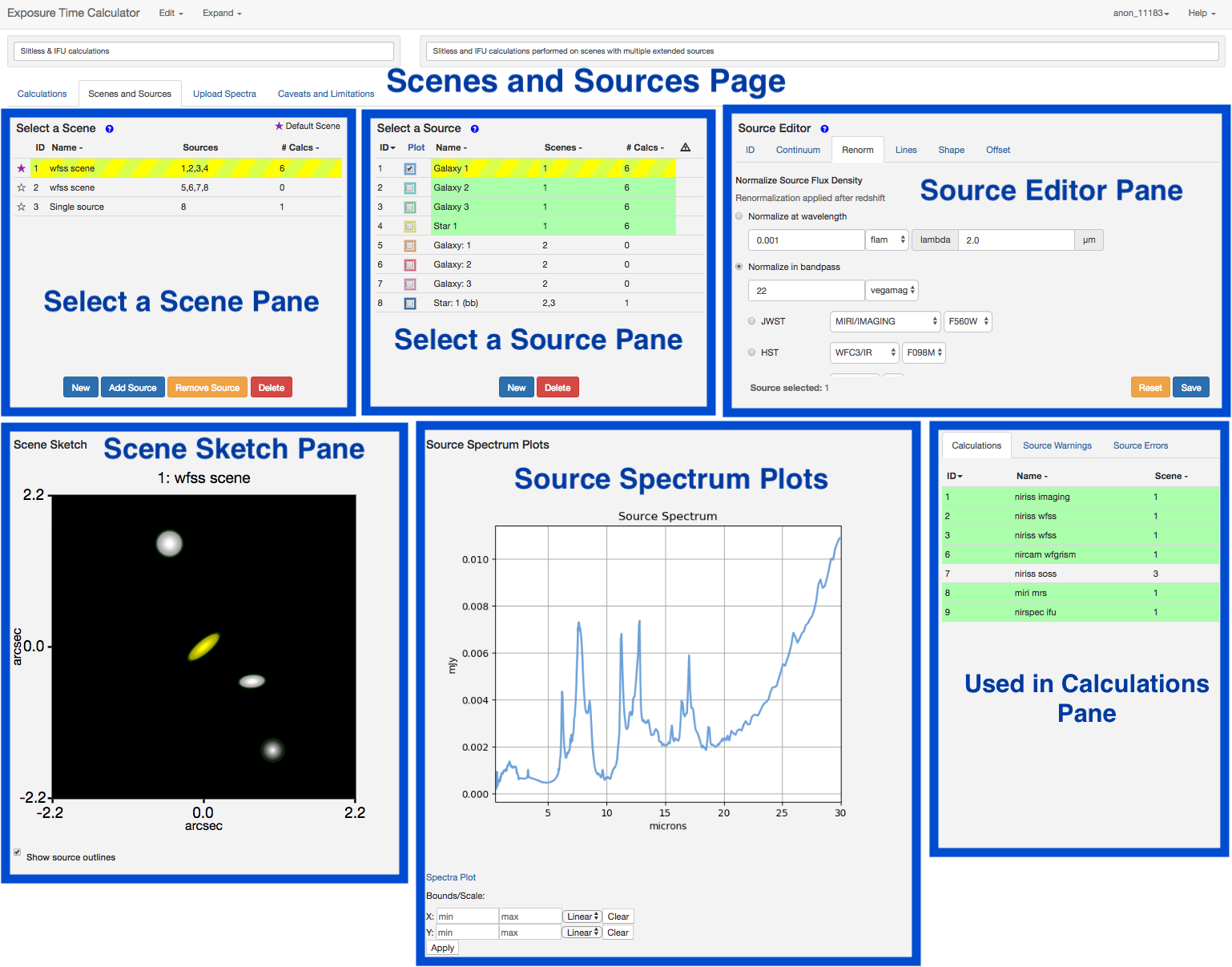
A new source can be created by clicking the NEW button within the Select a Source pane. This creates a new row in the source table with a default name, and shows the number of calculations equals 0 implying that this source is initially not associated with any scene or calculation. The default new source is a point source with a flat continuum. A new source may also be created by using the Copy Source option available in the Copy/Delete drop-down menu at the top of the Scenes and Sources page. This will create a new row in the source table with the same source name, but is not associated with any scene or calculation. Once the source is added to a scene and used in a calculation the information gets updated in the Select a Source pane. The scenes and sources are interactively linked.
Defining the properties of the new source
To modify the properties of the new source, first select it by clicking the row to highlight the source. The source editor has various tabs that can be used to change the source properties as described below. Note that the changes made using the source editor under each tab are applied to the selected source only when the SAVE button is activated.
ID
The ID tab allows the user to change the Scene Identify Information (scene name) and Source Identity Information (source name), as well as provide a descriptive comment about the scene.
Continuum
The Continuum tab allows the assignment of a spectrum to the new source by choosing a user-supplied spectrum, an analytic spectrum (such as a flat continuum, power-law continuum, or blackbody spectrum) or one of the template spectra (stellar spectra, extragalactic spectra, etc.) available in the spectral templates library.
The menu under Uploaded Spectra is populated with the list of user-supplied spectra.
When an analytic spectrum is selected the user will be presented with options to specify the parameters relevant to the chosen analytic spectrum, such as the flux units, the exponent for the power-law, or temperature for the black-body spectrum.
See the JWST ETC Source Spectral Energy Distributions for more details about the available template spectra.
There is an option for No Continuum which is useful for specific cases, such as when only spectral lines are being considered.
The Continuum tab also allows the user to specify the redshift of the source and the extinction to be applied. The extinction laws available are from Weingartner & Draine (2001) and Chapman et al. (2009). The extinction in magnitudes is specified in a chosen bandpass (V, J, H, or K).
Renormalization
The user can choose to normalize the spectral energy distribution for the source by providing the integrated magnitude (in AB magnitude or Vega magnitude units) of the source at a particular wavelength, or in a specified bandpass. The selection for JWST bandpass offers all the imaging filters on the JWST instruments. Alternatively, the user can also renormalize to the total magnitude in an HST (ACS, WFC3/UVIS, WFC3/IR, or NICMOS) bandpass or other available standard photometry filters (2MASS, Bessell, Cousins, Gaia, Johnson, MSX, SDSS, Spitzer, or WISE).
The normalization may also be specified in flux units either in flam (erg/s/cm2/Å), or fnu (erg/s/cm2/Hz), or in terms of spectral flux density in Jansky units.
For extended sources, if the normalization is selected to be in surface brightness units in the Shape tab, the units presented in the normalization tab will be per arcsec or per steradian.
The order of operations is to apply the redshift, then the extinction, then renormalize. Lines are added to the spectrum following renormalization, so line parameters must therefore be specified with respect to the redshifted, extincted, renormalized spectrum.
Lines
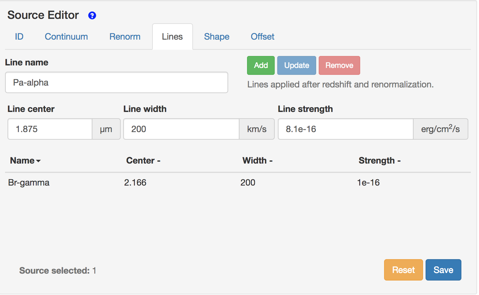
The user can add emission lines to the source continuum using the options available under the Lines tab (Figure 2). An emission line is defined by the following parameters: a user-defined line name, the line center in microns, a line width (FWHM) in km/s, and the line strength in erg/cm2/s. Note that the line strength corresponds to the integrated flux, not the peak flux. The line center should correspond to the redshifted wavelength because the lines are applied after redshift and renormalization. Once the line is added using the ADD button, the table of lines is populated with the input parameters. Multiple lines may be added to this list of lines to be applied to the source spectrum. To change the input parameters, select the emission line by clicking the row on the table, modify the parameters and click the UPDATE button. Lines may be deleted from the list by using the REMOVE button. Remember that the ADD, UPDATE, and REMOVE buttons will only modify the properties of the line that is being edited in the line list. For the emission lines to be applied to the source continuum, use the SAVE button.
Shape
The source morphology can be specified as a point source or an extended source. For extended sources, the flux distribution may be selected to be flat, 2D Gaussian, power-law or two flavors of Sersic profiles with a specified Sersic index (ranging from 1 to 4). In the case of an extended source, the parameters that specify the extent of the source in arcseconds must also be provided (such as, σx and σy for the 2D Gaussian, or Semi-Major Axis and Semi-Minor Axis for flat source or Sersic profiles). To assign the shape parameters to the source, use the Save button. See JWST ETC Defining an Extended Source for more details of the different flux distributions.
Offset
The offset has options to position the source anywhere in a scene. The spatial offsets are defined with respect to the center of the scene, and using large offsets will make the scene accordingly bigger and more computationally intensive. The default and maximum scene size depends on the instrument and mode as given in the table on the Scenes and Sources Page Overview. The offset parameters link the source and the scene, so it is important that the source is added to a scene for the offset parameters and orientation to take effect.
Examining the source
The sources that are created may be examined in the Scene Sketch and the source spectrum plots to ensure that the desired parameters for spectral characteristics, morphology, and location in the scene have been applied. The source spectrum plots display the spectrum for all the sources that have been selected using the checkboxes in the Select a Source pane. Use these plots to make sure that the source spectrum is correct (e.g., that the emission lines have been applied with the correct wavelength and line strength).
The Scene Sketch requires that the sources to be examined are already placed in a scene. This sketch can be used to examine the source location and orientation. The Scene Sketch is also useful to examine complex 2D source geometries that can be created by adding multiple sources to describe different components of an astronomical source or scene.
Deleting a source
A source can be removed from the current source library by using the DELETE button in the Select a Source pane. When the source to be removed is selected by highlighting the row in the source table, all the scenes that use the source will be indicated by the rows that are highlighted in green on the Select a Scene pane. Similarly, all the calculations which use the scenes containing the selected source will also be highlighted green in the "Used in Calculations" pane.
The green highlight is intended to make the user aware of the scenes and calculations that are affected by deleting or modifying the selected source. This feature is particularly important because the scenes, sources, and calculations are interlinked in the ETC.
References
JWST Exposure Time Calculator Tool
Chapman, N. L. et al. 2009, ApJ, 690, 496
The Mid-Infrared Extinction Law in the Ophiuchus, Perseus, and Serpens Molecular Clouds
Pontoppidan, K. M., Pickering, T. E., Laidler, V. G. et al., 2016, Proc. SPIE 9910, Observatory Operations: Strategies, Processes, and Systems VI, 991016,
Pandeia: a multi-mission exposure time calculator for JWST and WFIRST
Weingartner, J. C. and Draine, B. T. 2001, ApJ, 548, 296
Dust Grain-Size Distributions and Extinction in the Milky Way, Large Magellanic Cloud , and Small Magellanic Cloud

