NIRISS Single Object Slitless Spectroscopy
The single object slitless spectroscopy (SOSS) mode of JWST's Near Infrared Imager and Slitless Spectrograph (NIRISS) enables medium-resolution (R ≈ 700) spectroscopy at 0.6–2.8 μm, in 3 cross-dispersed orders for a single bright target. The SOSS mode is optimized to carry out time-series observations (TSOs).
On this page
See also: NIRISS Single-Object Slitless Spectroscopy APT Template, NIRISS SOSS Recommended Strategies, NIRISS SOSS Example Science Program
The single object slitless spectroscopy (SOSS) mode of NIRISS uses the GR700XD NIRISS grism to produce 3 orders of cross-dispersed spectra of bright targets in the wavelength range from 0.6–2.8 μm. The grism has a resolving power of R ≈ 700 at 1.25 μm in 1st order, and at 0.63 μm in 2nd order. The 3rd order will generally be too weak to be useful.
The SOSS mode is the time-series observation (TSO) mode for NIRISS and is thus optimized for spectroscopic applications requiring extremely high precision and spectro-photometric stability. It was especially designed to obtain spectra of transiting exoplanet systems around stars with J-band Vega magnitudes between 7 and 15. Instrumental stability is demanded because the spectrum of the exoplanet atmosphere must be disentangled from the spectrum of the host star by subtracting or dividing spectra obtained at different orbital phases.
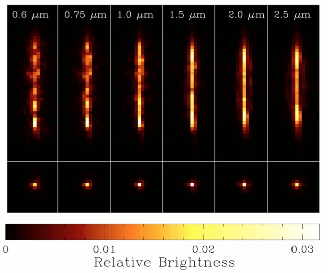
To achieve the levels of spectro-photometric precision and stability required by this sort of "differential spectroscopy," the GR700XD optical element incorporates a cylindrical lens that defocuses the spectral orders in the cross-dispersion direction. This smearing in the spatial dimension mitigates the effects of flat field errors and pointing jitter, while also allowing brighter objects to be observed without saturating the detector.
Spectral traces for SOSS
SOSS exposure sequence
See also: NIRISS SOSS Template APT Guide, NIRISS Target Acquisition, NIRISS SOSS Recommended Strategies, NIRISS Detector Subarrays, NIRISS GR700XD Grism
SOSS observations proceed in 2 steps:
- A target acquisition (TA) is performed to ensure that the spectroscopic traces fall on the desired region of the detector.
- NIRISS is configured for a SOSS exposure through the GR700XD grism and a (potentially long) set of integrations is obtained.
- Optionally, a second exposure through the F277W filter can be obtained. Such an exposure helps to isolate the 1st-order spectrum in the region where the 3 orders overlap spatially.
For the TA, NIRISS is configured with the CLEARP (for fainter targets) or NRM (for brighter targets) in the pupil wheel and the F480M filter in the filter wheel. Short integrations are taken, and the TA procedure autonomously determines the centroid of the object in the TA subarray. Accurate knowledge of the position of the source within this subarray is used to command a small slew that places it precisely at the "sweet spot," which ensures that the spectral traces for each order are located appropriately on the detector.
For the main science exposure (step 2 above), NIRISS is configured with the GR700XD element in the pupil wheel and the CLEAR element in the filter wheel, and a specific subarray is selected. A typical SOSS observation consists of staring at a single target for the duration of a scientifically interesting event like an exoplanet transit or even an entire orbit of an exoplanet. Since the exoplanet hosts are usually bright stars, individual integrations may be short; and many integrations may be required to cover the duration of the event. More details on the SOSS operations can be found on the NIRISS operations page.
SOSS subarrays
See also: NIRISS Detector Subarrays, JWST ETC SOSS Spectral Extraction Strategy
Words in bold are GUI menus/
panels or data software packages;
bold italics are buttons in GUI
tools or package parameters.
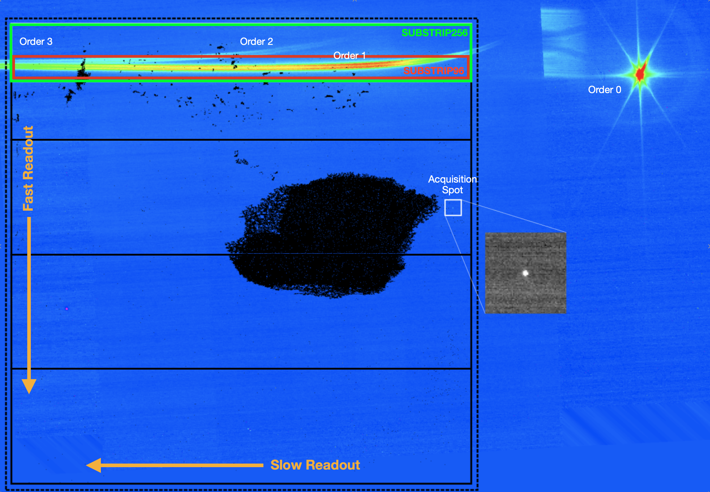
- The "nominal" SUBSTRIP256 subarray is 2048 × 256 pixels, which is big enough to capture the 1st and 2nd orders; the 3rd order may be too weak to be useful. Stars as bright as J ≈ 8.4 or 6.3 (Vega magnitudes) can be observed without saturating in 1st or 2nd order, respectively.
- The "bright" SUBSTRIP96 subarray is 2048 x 96 pixels, and only captures the 1st order. Stars as bright as J ≈ 7.4 (Vega magnitudes) can be observed without saturating.
The "bright" subarray is only intended for observations of the brightest stars (J ≈ 7.4 in the Vega system) for which the additional wavelength coverage provided by the 2nd order is not essential.
The target acquisition for SOSS mode is performed in a 64 × 64 subarray centered on the "sweet spot."
As an option for more general applications of the SOSS mode, the entire detector can also be read out.
SOSS dither patterns (or lack thereof)
See also: NIRISS Dithers
The level of spectro-photometric stability and precision required by exoplanet transit spectroscopy can only be achieved if the same pixels are illuminated for the duration of an observation. Consequently, SOSS observations are not dithered.
However, to recover some of the usual benefits of dithering, the GR700XD grism incorporates a cylindrical lens on its "light input" surface that defocuses spectral traces in the spatial direction by ≈25 pixels. This additional smearing over many pixels in the spatial direction reduces the effect of any small shifts (due, e.g., to the rotation of the field of view during a long "staring" observation) that might cause different pixels to be illuminated. It also reduces the effect of intra-pixel sensitivity variations and detector blemishes. Redistributing dispersed light over many pixels has the additional benefit of allowing brighter targets to be observed before the onset of saturation.
References
Goudfrooij, P., Albert, L., Doyon, R., 2015, STScI Newsletter, Volume 32, Issue 01
The Single-Object Slitless Spectroscopy Mode of Webb's NIRISS Instrument


