MIRI Optics and Focal Plane
The JWST Mid-Infrared Instrument (MIRI) optical light path divides into 2 channels: a spectrometer and an imager. The spectrometer is also configured for integral field unit (IFU) spectroscopy.
On this page
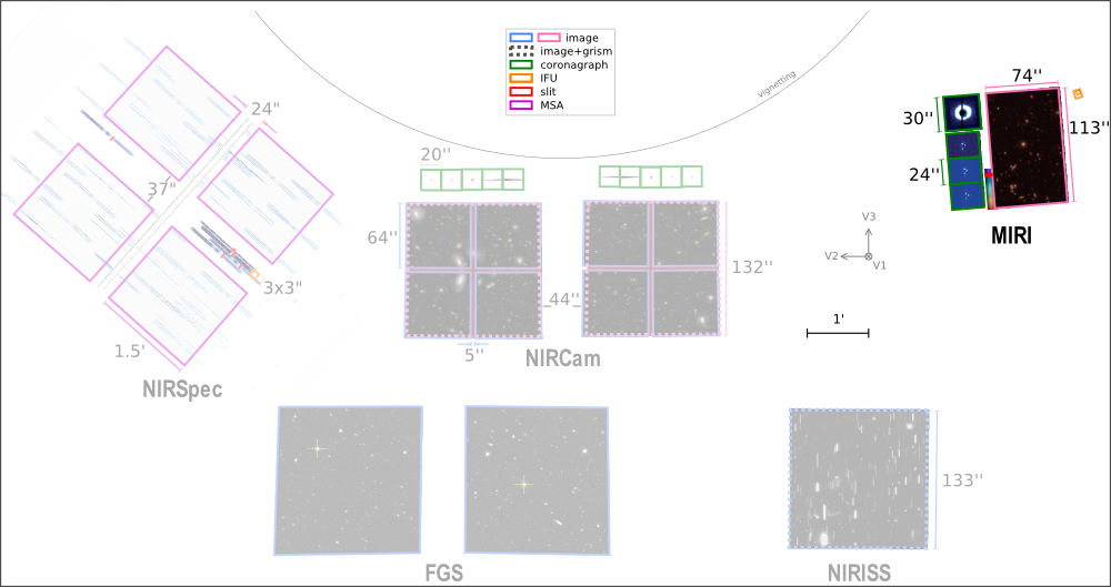
Figure 1 shows the Mid-Infrared Instrument (MIRI) field of view in relation to fields of view of other instruments.
MIRI's pick-off mirror, in front of the JWST optical telescope assembly focal plane, directs the MIRI field of view towards the imager. A small fold mirror adjacent to the imager light path picks off the small (up to 6.6'' × 7.7'') field of view of the spectrometer. A second fold in the spectrometer optical path is used to select either the light from the telescope or from the MIRI calibration system.
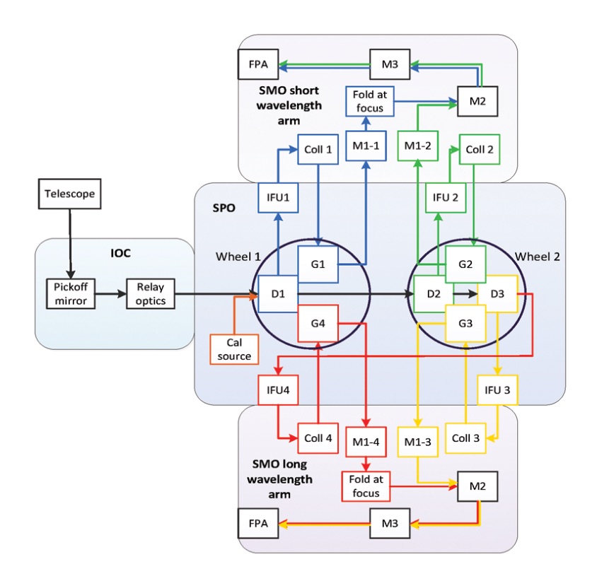
Overview of the MIRI optical architecture, showing the primary components (detailed components for MIRIM and MRS are given below). The science light path through the MIRI modules are shown in blue. © Wright et al. 2015 (Figure 2).
Imager (MIRIM)
See also: MIRI Imaging, MIRI Low Resolution Spectroscopy, MIRI Coronagraphic Imaging
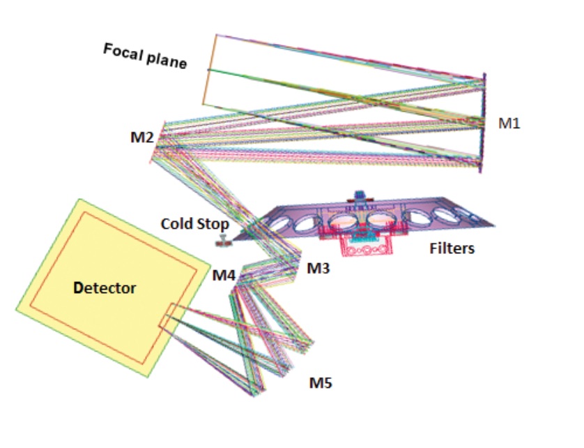
The optics are configured to place the entrance focal plane just outside the MIRIM housing; this allows the focal plane module (which houses the coronagraph masks and low-resolution spectrometer slit) to be bolted directly to the housing in a very simple interface.
Inside MIRIM, the field of view (FOV) is partitioned into 3 functional areas on the instrument focal plane: imager, coronagraph, and low-resolution spectrometer.
First, the light is collimated. At the pupil image formed by the collimator, a filter wheel holds the following: filters for both the imager and coronagraphs, a prism assembly for the low-resolution spectrometer, a blank for dark current measurements, and a pupil imaging lens. This entrance focal plane is imaged onto the detector using a three-mirror anastigmat camera with separate areas of the detector being dedicated to the imaging, coronagraphy, and spectroscopy functions. The region of the focal plane for each function is selected by a fold mirror close to the telescope focal plane.
Medium-resolution spectrometer (MRS)
See also: MIRI Medium Resolution Spectroscopy
The MRS provides diffraction-limited integral field spectroscopy (IFU) between 4.9 to 27.9 μm over a FOV of up to 6.6'' × 7.7''. This mode consists of 2 modules: the spectrometer pre-optics (SPO) and spectrometer main optics (SMO).
The SPO spectrally splits the light into 4 spectrometer channels and spatially reformats the rectangular fields of view into slits at the entrance of the SMO. The SMO collimates the light from the IFU, presents the collimated light to gratings (mounted in the SPO) to disperse the light, and images the resulting spectrum onto the 2 focal plane arrays (FPA). All 4 spectrometer channels are observed simultaneously, but each exposure will only include one-third of the available spectral range depending on the chosen grating settings. The SMO is divided into 2 separate arms. The short wavelength arm images the final spectra from the short channels (channel 1 and 2) onto opposite halves of the MIRIFU_SHORT detector, while the long wavelength combines channel 3 and 4 onto opposite halves of the MIRIFU_LONG Detector (see MIRI Medium Resolution Spectroscopy for more details on the resulting MRS spectra).
Spectrometer pre-optics (SPO)
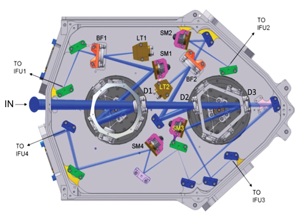
Inside the SPO, the light is divided into 4 different wavelength channels using 3 dichroics.
Each channel has its own dedicated integral field unit (IFU) and the spectra from each of the 4 channels occupy half of one of the 2 MRS detectors.
Each channel is split, by an additional dichroic chain, into 3 sub-bands that are observed sequentially by rotation of 2 wheels that carry the 3 wavelength sorting dichroics and the 12 dispersion gratings in a very compact and efficient configuration.
The position of the input pupil and fold mirror are labelled "IN." The locations of blocking filters (BF), light traps (LT), powered mirrors (SM) and dichroics (D) are shown. After the light has been divided into the appropriate spectral ranges, it is output to the integral field units (IFU) for the four spectrometer channels. © Wells et al. 2015 (Figure 3)
Integral field units (IFUs)
See also: JWST Integral Field Spectroscopy
The optical path through the IFUs begins with the 4 toroidal mirrors, which comprise the anamorphic pre-optics (APO) module. The APO re-images the input focal plane (8" × 8") onto the image slicer mirror. Light exits the IFU through individual pupil masks for each beam, then through individual slitlets. Reimaging mirrors behind the slitlets relay the beam to the input of the appropriate spectrometer.
Spectrometer main optics (SMO)
The SMO consists of a short wavelength arm and a long wavelength arm which perform the following 3 functions:
- collimation of the output beams of one of the 4 IFUs,
- dispersion of the collimated beam with diffraction gratings, and
- imaging of the resulting spectrum onto one-half of one of the 2 focal plane arrays.
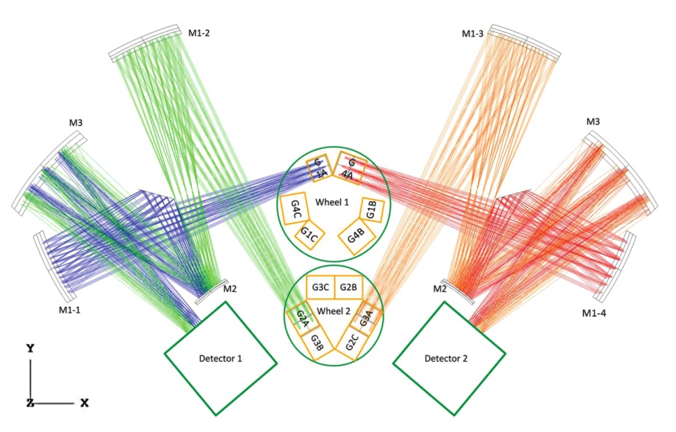
One of the 2 spectrometer arms includes the 2 short wavelength channels (channels 1 and 2); the other has long wavelength channels (channels 3 and 4). Each spectrometer arm uses 6 gratings (to allow for any combination of 2 wavelength channels and 3 sub-band exposures). Figure 6 shows the optical path from the gratings (located on 2 wheels in the SPO) to the detectors. The dispersed beams are imaged by three-mirror-anastigmat (TMA) camera systems (M1–M2–M3). Folding flats reflect the channel 1 and channel 4 beams such that the combined (channel 1 + 2) and (channel 3 + 4) beam pairs are imaged onto opposite halves of the detectors.
While all 4 channels are observed simultaneously, each exposure will only cover one-third of the available wavelength range of each channel in a single grating configuration. Therefore a single MRS exposure will cover 4 discontinuous wavelength intervals (the first, middle or last thirds of each channel). For complete spectral coverage, 3 different grating settings must be observed; SHORT (A), MEDIUM (B), and LONG (C). Combining the 4 channels and 3 grating settings will utilize all 12 gratings and result in 12 different wavelength sub-bands, increasing in wavelength from "1A" to "4C."
References
Wells, M. et al. 2015, PASP, 127, 646
The Mid-Infrared Instrument for the James Webb Space Telescope, VI: The Medium Resolution Spectromete
