NIRSpec Multi-Object Spectroscopy
One showcase observing mode of JWST is the NIRSpec multi-object spectroscopy (MOS) mode using the micro-shutter assembly (MSA). The MSA can obtain simultaneous spectra of many science sources within a 3.6' × 3.4' field of view.
On this page
See also: JWST Multi-Object Spectroscopy, NIRSpec MSA Planning Tool, MPT, MOS Roadmap.
See also: Using NIRSpec MOS mode: Summary and Helpful Hints Video Tutorial, NIRSpec Multi-object Spectroscopy Overview and Tool Demo Video Tutorial.
The JWST NIRSpec multi-object spectroscopy (MOS) mode provides multiplexing 0.6–5.3 μm spectroscopy capabilities over a 3.6' × 3.4' field of view. This mode uses tiny configurable shutters in the micro-shutter assembly (MSA) to acquire dozens to hundreds of spectra of astronomical sources within a single exposure. This is a very powerful feature for spectroscopic surveys. For example, potential use cases for the NIRSpec MOS mode include but are not limited to: spectral characterization of the faintest objects in our universe, surveys to investigate galaxy formation and evolution, stellar population studies, star cluster formation, and the evolution and properties of extended solar system bodies.
The NIRSpec MSA consists of 4 quadrants of 365 × 171 shutters that can be individually opened and closed to create the spectral slit configurations for this multi-object spectroscopy mode. In Figure 1, the 4 NIRSpec MSA quadrants are plotted on a Hubble Space Telescope WFC3 F555W image of the Tarantula Nebula in the Large Magellanic Cloud.
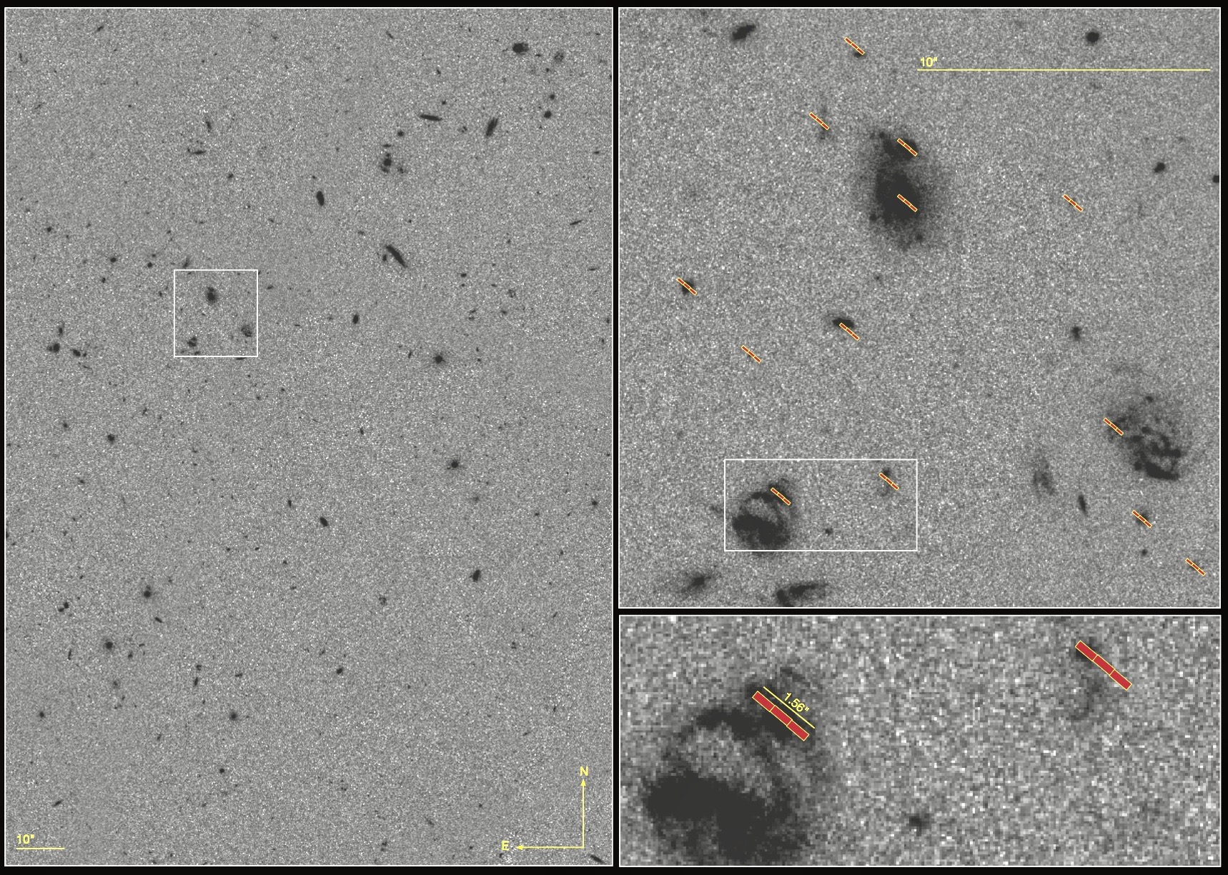
The NIRSpec MSA can be opened in contiguous columns of several shutters to create the so-called “slitlets” to acquire MOS spectra of science sources of interest. Figure 2 shows a zoomed-in view of several 3-shutter slitlets, configured to open on (faint) sources, over-plotted on the Hubble Ultra Deep Field WFC3 UVIS image.
MSA shutters
See also: NIRSpec Micro-Shutter Assembly, NIRSpec MOS Recommended Strategies, NIRSpec MSA Shutter Operability
The MSA consists of 4 quadrants, each with 171 rows of 365 shutters, totalling ~250,000 shutters. The 4 quadrants are labelled Q1–Q4, as shown in Figure 3. The open area of each MSA shutter is 0.20" × 0.46" (width in the dispersion direction × cross-dispersion direction).
MSA shutters are mounted on a fixed support grid. Support bars between all shutters are 0.07"" wide so that the shutter pitch (center-to-center distance) is 0.27" in the dispersion direction and 0.53" in the spatial (cross-dispersion) direction.
The area in each MSA quadrant is about 95" in the dispersion (X) direction by 87" in cross-dispersion (Y), and the total extent of the MSA sky field of view is 3.6' × 3.4'.
MSA quadrants are separated from one another by ~23" along the dispersion (X) axis (that is, between the inner edges of the yellow-shaded shutter arrays shown in Figure 3 from the right edge of Q3 to the left edge of Q1, and similarly between Q4 and Q2). Note that this gap is not the same as the gap between detectors in the dispersion (X) direction, which is ~18". It is the detector gap that is responsible for missing wavelength information in spectral observations with the MSA. The MSA mounting plate also separates Q1 from Q2, and Q3 from Q4, by about 37" in the spatial (Y) direction. The fixed slits in this 37" gap between quadrants are always open.
The ~250,000 shutters can be individually selected to open or close to create an MSA configuration. The NIRSpec MSA is configured to open sets of science shutters using a 2-step process: (1) the MSA magnet arm sweeps across the MSA to open all shutters in the quadrants, then (2) the magnet moves back across the quadrants to close or leave open shutters as commanded by the user. This configuration process takes about 90 seconds.
A few shutter-based considerations for MOS observing:
- Some of the shutters in the NIRSpec MSAs are unusable for science, with a population vignetted by the instrument field-stop, others deliberately masked to prevent electrical shorts in the complex control circuitry, and others permanently "failed open" or "failed closed" due to mechanical deformities. For more information on the hardware shutter operability, please see NIRSpec Micro-Shutter Assembly. The NIRSpec observation planning software will search for optimal MSA shutter science configurations and automatically plan around all inoperable shutters. For more details on the MSA operability visualization during configuration planning and optimisation, please see NIRSpec MSA Shutter Operability.
- In addition to failed open shutters, even operable shutters commanded shut during an exposure have finite contrasts. This results in small light leaks that can contaminate observed spectra from planned sources. This is the same problem that affects IFU spectra. Further details about the problem and mitigation strategies, similar to those for IFU observations, are described in the NIRSpec Micro-Shutter Assembly, NIRSpec MSA Leakage Correction for IFU Observations, and MSA Leakage Subtraction Strategies articles.
- The small size of individual NIRSpec MSA shutters means that detailed and careful planning must be carried out for most observations of compact sources. High-quality astrometry (to 5–10 mas) is not required but strongly recommended, particularly for sources smaller than the size of a shutter. The accuracy of target acquisition, and hence the flux calibration, is directly related to the input astrometric accuracy. The best astrometry is likely to come from HST images of the field or a JWST NIRCam mosaic image.
- Larger or extended sources may be observed by configuring the MSA into a long slit or other suitable geometry. Detailed astrometry is not required in this use case, but pointing precision will be poorer.
Spectral configurations
Words in bold are GUI menus/
panels or data software packages;
bold italics are buttons in GUI
tools or package parameters.
All available disperser and filter combinations can be used in NIRSpec MOS mode. Table 1 below outlines usable instrument configurations, spectral resolutions, and wavelength ranges.
Table 1. Spectral configurations available in NIRSpec MOS mode
| Disperser-filter combination | Nominal resolving power | Wavelength range † (μm) |
|---|---|---|
| G140M/F070LP | ~1,000 | 0.70–1.27 |
| G140M/F100LP | 0.97–1.84 | |
| G235M/F170LP | 1.66–3.07 | |
| G395M/F290LP | 2.87–5.10 | |
| G140H/F070LP | ~2,700 | 0.81–1.27 |
| G140H/F100LP | 0.97–1.82 | |
| G235H/F170LP | 1.66–3.05 | |
| G395H/F290LP | 2.87–5.14 | |
| PRISM/CLEAR | ~100 | 0.60-5.30 |
† Wavelength range values presented here are approximate. Note that the nominal spectral ranges for medium and high-resolution dispersers may be shortened due to red-end detector cutoffs. The cutoff wavelengths depend on the target aperture location (slit or shutter). Detailed limits on the wavelength ranges and gaps are found in the ETC.
MSA spectra are projected onto the 2 NIRSpec detectors (NRS1 and NRS2). In the NIRSpec MOS mode, some shutters will not capture the entire spectral range at the high resolution, R ~ 2,700, configurations. This is because the right-most MSA shutters in MSA quadrants 1 and 2 (Figure 3) project the longest wavelengths beyond the right edge of detector NRS2 in the R = 2,700 configurations. Alternatively, R ~ 1,000 spectra do not extend past the right-hand side of NRS2 (see Figure 5).
Detector wavelength gaps
See also: NIRSpec MOS Wavelength Ranges and Gaps.
In the MOS mode, there are gaps in spectral coverage caused by the physical distance between the 2 detectors, referred to as detector wavelength gaps. The range of wavelengths lost in the gap differs for different shutters in the MSA since the spectra from different shutters map to different locations on the detectors. Unlike fixed slits (FS) and integral field unit (IFU) observations, which suffer wavelength gap losses only in the R ~ 2,700 high spectral resolution mode, all grating and filter combinations in the MOS mode have shutters that lose wavelengths to the gap.
The detector wavelength gap discussed here is due to the detector gap and not from the gap between quadrants of the MSA (both gaps are shown in Figure 3).
Subarrays
NIRSpec MOS mode exposures are only acquired in full frame 2048 × 2048 detector pixel readout; no subarrays are used.
Exposure specification
See also: NIRSpec Detectors, NIRSpec Detector Recommended Strategies
NIRSpec MOS exposure times are tied to the timing of the detector readout patterns. There are 4 readout patterns available for NIRSpec MOS observations:
- NRSRAPID
- NRS
- NRSIRS2RAPID
- NRSIRS2
The readout patterns are split over 2 readout modes: (1) traditional and (2) improved reference sampling and subtraction (IRS2). The traditional mode, which is used for the NRSRAPID and NRS readout patterns, is similar to the detector readout for NIRCam and NIRISS. In full detector readout, NRSRAPID has a single frame (10.7 s), and NRS averages 4 frames (42.8 s).
The IRS2 mode, which is used for the NRSIRS2RAPID and NRSIRS2 readout patterns, intersperses reference pixels within the science pixel reads to improve noise characteristics achievable during data processing, resulting in longer frame times and higher data volumes. Like the traditional readout, the NRSIRS2RAPID is a single frame, but unlike the traditional readout equivalent, NRSIRS2 has 5 frames averaged into a single group. These IRS2 readout patterns improve performance and sensitivity in long-exposure MOS observations of faint objects.
Additional information on NIRSpec MOS exposure specification and how this translates to exposure time and sensitivity can be found using the JWST Exposure Time Calculator (ETC). Users interested in determining which readout pattern is best for their science should refer to the NIRSpec Detector Recommended Strategies article.
Options for dithering
See also: NIRSpec MOS Dither and Nod Patterns, NIRSpec Dithering Recommended Strategies, NIRSpec MOS Recommended Strategies.
Most observations with JWST will require dithering. This is especially true for NIRSpec since the PSF is undersampled at most wavelengths. The NIRSpec MOS mode provides 2 options for creating offsets or dithers:
- Nodding: The telescope can be repositioned slightly between exposures to place the sources in different shutters within the slitlets of an MSA configuration.
Fixed dithers: Larger telescope dithers which position the sources onto different shutters of the MSA and their spectra onto different areas of the detectors.The NIRSpec MOS dithering page and the NIRSpec MOS Recommended Strategies page provide an in-depth review of the available options mentioned here. Users interested in learning which dithering strategies are recommended for their science should read the NIRSpec Dithering Recommended Strategies article.
What do NIRSpec MOS data look like?
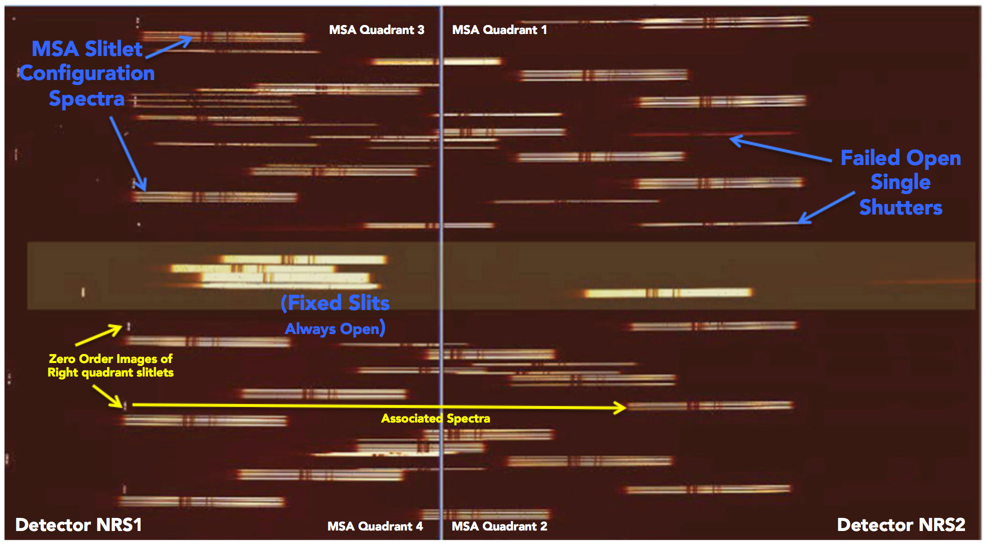
Figure 4 shows NIRSpec MOS mode data acquired with a ground calibration test lamp using the R = 1,000 G140M/F100LP short wavelength spectral configuration. The 4 MSA quadrant spectra are shown. This observation was acquired with a special 5-shutter calibration-only slitlet pattern that had 3 shutters open with 2 closed in between them. Two of the slitlet configurations are highlighted. Failed open shutters cause contaminating single shutter spectra. The MSA planning software is designed to automatically optimize an MSA configuration around failed open shutters so that science spectra of observed sources are not contaminated by dispersed light from these shutters.
References
Böker, T. 2016 ESAC JWST "On Your Mark" Workshop (ppt) (pdf)
The NIRSpec Multi-Object Spectroscopy (MOS) mode
Dorner, B., Giardino, G., Ferruit, P. et al. 2016, A&A, 592, A113
A model-based approach to the spatial and spectra calibration of NIRSpec onboard JWST
Ferruit et al. 2022, A&A, 661, A81
The Near-infrared spectrograph (NIRSpec) on the James Webb Space Telescope II. Multi Object Spectroscopy (MOS)
Kutyrev, A.S., Collins, N., Chambers, J. et al. 2008 SPIE, 7010, 70103d
Microshutter arrays: High contrast programmable field masks for JWST NIRSpec
Rawle, T 2022 SPIE, Volume 12180, id. 121803R 15 pp. (2022)
In-flight performance of the NIRSpec micro shutter array


