JWST ETC Point Spread Functions
The JWST Exposure Time Calculator (ETC) uses point spread functions (PSFs) from a precomputed library of PSFs produced by WebbPSF. (For more details on WebbPSF's optical model, check out the WebbPSF documentation pages.)
On this page
The PSF library
Each instrument aperture is represented by a precomputed set of roughly 30 PSFs, generated at log-normal wavelength intervals that span the entire wavelength range of all filters and dispersers used with that aperture. With the exception of coronagraphic imaging, all PSFs are generated on-axis, centered on the detector, and are thus devoid of any optical aberrations that may impact real PSFs at locations far from the detector center. Given that the ETC models sources close to the center, the effect is likely to be minimal.
Coronagraphic observations have multiple sets of roughly 30 PSFs each, generated at log-normal wavelength intervals in multiple spatial locations, to account for the effects of coronagraphic spots.
The PSFs are generated to relatively small sizes—the largest are the MIRI 4QPM PSFs (used in MIRI coronagraphic imaging), which cover 8.91" on a side; the smallest are NIRCam SW imaging PSFs that are only 1.59" on a side. Nevertheless, the PSFs cover more than 92% of the total flux (excepting MIRI imaging, minimum 78%).
ETC version 3.0 uses WebbPSF version 1.1.0, WebbPSF Data version 1.1.0, and POPPY version 1.0.3 to construct the PSF library for all science instruments (MIRI, NIRCam, NIRISS, and NIRSpec). With the exception of 2 new NIRCam PSFs added to support the F150W2 filter, the PSF library is unchanged from ETC 2.0.
How the library is used
For a given observation, the entire set of PSFs for a given aperture are loaded into the ETC.
The scene generation process creates a cube with both spatial and wavelength dimensions for each source in the scene. It then takes those cubes and convolves each wavelength plane with the appropriate PSF; this PSF is produced by interpolating the set of PSFs at the specific wavelength of the cube slice. Thus, the apparent PSF in the output 2D images is the sum of multiple wavelength-dependent PSFs, scaled by the filter throughput curve.
The model cubes for each scene are then added together to form a combined scene cube, which is then "observed" onto a detector, and results extracted by use of the strategy.
The reason that the PSF convolution is done before the combination of all of the sources is to make it easier to use a positionally-dependent PSF, which is done for coronagraphy.
Position-dependent coronagraphic PSFs
Words in bold are GUI menus/
panels or data software packages;
bold italics are buttons in GUI
tools or package parameters.
MIRI
4QPMs
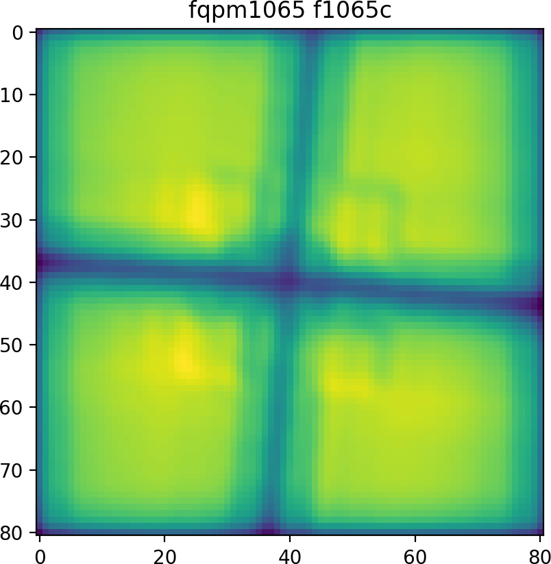
The MIRI 4-quadrant masks (4QPM) are selectable in the ETC as 4QPM/F1065C, 4QPM/F1140C, and 4QPM/F1550C. They are used for coronagraphic imaging and have eight-fold symmetry: they can be reflected across each of the quadrant axes and across the primary axes of the detector (which is approximately correct). PSFs were generated in a triangular shape, covering the 0%, 33%, 66%, and 99% unobscured positions. The positions take into account the roughly 5° clockwise rotation of the MIRI masks.
Bottom: a dense grid of point sources run through the ETC traces out the resulting shape of the MIRI 4QPM obscuring elements.
LYOT/F2300C
The MIRI LYOT/F2300C mask is assumed to have radial symmetry. PSFs were generated along the Y-axis, at points that are 0%, 25%, 50%, 75%, and 99% of unobscured flux.
Bottom: a dense grid of point sources run through the ETC traces out the resulting shape of the MIRI LYOT/F2300C obscuring element.
NIRCam
MASKSWB, MASKLWB
The NIRCam MASKSWB and MASKLWB masks are assumed to have vertical symmetry. They are tapered wedges (where MASKSWB tapers toward negative X, and MASKLWB tapers toward positive X), such that each filter has an optimal position along the wedge where a point source is just barely fully obscured. Sets of 5 PSFs were generated at 1" intervals along the wedge and at those optimal positions, and positions above the bar that are 0%, 3 mas offset, 1%, 10%, 50%, 75%, and 99% of unobscured flux.
Bottom: a dense grid of point sources run through the ETC traces out the actual resulting shape of the NIRCam MASKLWB obscuring element (tapering toward positive X).
MASK210R, MASK335R, MASK430R
The NIRCam MASK210R, MASK335R, and MASK430R masks are assumed to have radial symmetry. PSFs were generated along the Y-axis, at points that are 0%, 3 mas, 1%, 10%, and 99% of unobscured flux.
Bottom: a dense grid of point sources run through the ETC traces out the resulting shape of the NIRCam MASK335R obscuring element.
References
WebbPSF webpage


