JWST Fine Guidance Sensor
JWST's Fine Guidance Sensor (FGS) provides data for science attitude determination, fine pointing, and attitude stabilization using guide stars in the JWST focal plane. Absolute pointing and image motion performance is discussed on the JWST Pointing Performance page.
On this page
JWST's Fine Guidance Sensor (FGS) is a near-infrared (NIR) camera residing in the Integrated Science Instrument Module (ISIM). It has a passband from ~0.6 to 5.0 μm and operates at a temperature of ~37 K, similar to the near-infrared science instruments. The FGS has 2 channels, Guider1 and Guider2, each with 2.3′ × 2.3′ field of view (FOV) imaged onto a 2048 × 2048 pixel array, with the central 2040 × 2040 pixels being light sensitive. The outer four rows and columns of pixels serve as reference pixels for bias measurements. The arrays have 18 μm physical pixels and a pixel scale of ~0.069".
The role of the FGS is to:
- identify and acquire a guide star, measure its position in one of the 2 guider channels, and provide this data to the JWST attitude control subsystem (ACS) for attitude determination.
provide fine pointing data to the ACS for attitude stabilization. The FGS can provide this data for both fixed target pointings and for moving target observations.
Guide star position data is used by the ACS for absolute (right ascension and declination) pointing knowledge and pointing control in the plane of the sky (pitch and yaw). ACS uses the data from off-axis star trackers to control the spacecraft’s roll orientation.
In addition to its critical role in executing observations, the FGS also served as an integral part in the commissioning of the JWST Observatory. FGS pointing data for each science observation are archived and may be valuable for post-observation data analysis; see JWST Fine Guide Stability for information on guiding data products, measuring jitter, and jitter tools.
Unlike on HST, the Fine Guidance Sensors on JWST are used exclusively for guiding and calibration. Thus, they are not available for science proposals by general observers.
Figure 1. FGS fields of view, highlighted, in the JWST focal plane
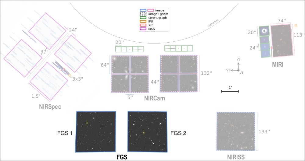
Click on the figure for a larger view.
Observational capabilities
The FGS has an unfiltered passband from ~0.6 to 5.0 μm. Each focal plane array is a 2048 × 2048 HgCdTe sensor chip assembly that has a 2.3’ × 2.3’ FOV after correcting for internal field distortions. The central 2040 × 2040 pixels are light sensitive; the 4 outermost rows and columns are reference pixels for bias measurements. However, the usable FOV for guide star identification and guiding is 2.20' × 2.20' in order to provide sufficient light-sensitive pixels for flat field corrections for potential guide stars near the edge of the FOV.
The FGS has neither a shutter nor a filter wheel; therefore, its detectors are always exposed to the sky.
The JWST proposal planning system currently uses the latest version of Guide Star Catalog (GSC), which includes improvements over previous versions of the catalog to astrometry, photometry, and number and distribution of stars that are available. For additional information, please refer to the JWST Guide Stars and JWST Guide Star Catalog Updates articles.
FGS optical design
The optical assembly of the FGS is shown in Figure 2. Light from the telescope is focused onto the pick-off mirror (POM), collimated by the 3-mirror assembly (TMA), and focused by an adjustable fold mirror (fine focus mechanism) onto the 2 focal plane arrays. The fine focus mechanism allows tuning of FGS focus.
Figure 2. Layout of the FGS optical components on the optical bench

© Honeywell.
FGS operations
FGS has 3 operating modes: "OFF", "STANDBY",† and "OPERATE". When in OPERATE mode, FGS has 5 software functions: "Calibration", "Identification", "Acquisition", "Track", and "Fine guide". The Calibration function allows the FGS to obtain necessary data for calibration by the ground system, while the remaining functions enable the identification, acquisition, and tracking of a guide star. These flight software functions are briefly described below, and illustrated schematically in Figure 3.
Calibration
In order to be able to calibrate the FGS, the ground system requires data collected with the "calibration" function. In this mode, the FGS acts like a camera, obtaining full frame or subarray images with one guider while the other tracks a guide star. These data are then used to measure and correct for geometric distortion, intra-pixel non-uniformity, flat field response, bias, bad pixels, and other performance characteristics. The "calibration" function is only available for calibration observations.
Identification
At the conclusion of a spacecraft slew, the telescope is pointing at the sky such that the selected guide star is in the field of view of one of the FGS detectors and the science target is in the desired science instrument, though not yet at the precise attitude for the scientific observation. To assure that the correct guide star is acquired, the FGS obtains an image of the sky and compares the observed positions of stars (and any other luminous objects) to a catalog of objects using a pattern-matching algorithm. To minimize smearing, the "identification" images are obtained in a sequence of "strips": 36 subarrays of 2048 × 64 pixels with a photon counting time of 0.3406 s each.
Acquisition
The approximate location of a guide star on the FGS detector is measured using the flight software "identification" function, or is determined at the end of a small angle maneuver that offsets the guide star from a previously known location in the FGS FOV. This is followed by executing the "acquisition" function. A 128 × 128 pixel (8.8” × 8.8”) subarray is centered at the expected position of the guide star. Images of the guide star within this subarray are obtained and autonomously analyzed by the FGS to locate the star. A second set of measurements using a 32 × 32 pixel (2.2" × 2.2") subarray, centered on the guide star position, is obtained. The FGS reports the position and intensity of the guide star to the ACS; this information is used by the ACS to update its knowledge of the spacecraft’s current attitude, and to bring the pointing of the telescope to within 0.1" (1-σ radial) of its commanded position.
Track
Following the successful completion of the "acquisition" function, and ACS’s corrective maneuver of the observatory pointing, the FGS executes the "track" function. The FGS places a 32 × 32 pixel (2.2" × 2.2") subarray on the expected location of the guide star. High cadence subarray images are obtained from which the guide star’s position centroid is determined and reported to ACS every 64 ms. Once the guide star is within ~0.06" of its desired location, the FGS can transition to "fine guide" mode.
In "track" mode the FGS adjusts the position of the 32 × 32 pixel subarray on the detector to remain centered on the guide star if the guide star moves. Thus, "track" mode is used for moving target observations.
Fine guide
When the FGS transitions from "track" to "fine guide," a fixed 8 × 8 pixel (0.5" × 0.5") subarray is centered on the guide star position. The guide star centroid is computed from each subarray image and sent to the ACS every 64 ms, controlling the observatory pointing in a closed loop. In "fine guide" mode, the subarray location is fixed and cannot be changed without transitioning through the operating mode "STANDBY"1, which requires exiting fine guidance control and starting over in "track" mode.
Once in fine guide control, the absolute pointing accuracy of JWST with respect to the celestial coordinate system will be determined by the astrometric accuracy of the Guide Star Catalog and the calibration of the JWST focal plane model.
† In "STANDBY," the operations scripts subsystems (OSS) software is running and the guider is waiting, ready to transition to the operating mode "OPERATE" and execute a commandable function such as "identification." The FGS flight software (FSW) controls the physical and electrical conditions to which the guider's performance is sensitive. In "STANDBY," the FGS flight software will be capable of sending and receiving commands, data, and software updates.
Figure 3. Guiding Overview for a Typical JWST Visit

Click on the figure for a larger view.
Subarrays
Each of the operational modes uses a different sized subarray and readout pattern. The frame readout time for each subarray can be calculated using the following equation:
| t_{frame} = \Bigg(\frac{N_{columns}}{N_{outputs}} + C_{overhead}\Bigg) \times (N_{rows} + 1) \times 10 \mu s. |
where N_{outputs} is the number of amplifiers used in the subarray, equal to 4 for CAL full frame and ID and 1 for CAL subarrays and other functions; where C_{overhead} is a constant that accounts for electronic overhead, equal to 12 for ACQ1 or 6 for all other functions; and where the number of rows and columns N_{rows} and N_{columns}are as specified in Table 1 below.
FGS data utilizes correlated double sampling (CDS) to correct for detector effects within integrations, a method in which the 0th read is subtracted from the 1st read. The time between reads, or CDS time, is a function of the readout pattern and the frame readout time:
| t_{CDS} = (N_{DROP} + 1) \times t_{readout} |
where N_{DROP} is the number of dropped frames between reads and t_{readout} is the frame readout time.
Table 1. Subarray and readout definitions for each function
| Name | Abbreviation | Subarray | Integration readout pattern | Frame readout time (s) | CDS time (s) |
|---|---|---|---|---|---|
| Calibration | CAL | Variable‡ | RESET READ DROP x n READ2 | Variable‡ | Variable‡ |
| Identification | ID | 2048 x 64 x 36 (strips)§ | RESET READ READ RESET READ READ | 0.3406 | 0.3406 |
| Acquisition 1 | ACQ1 | 128 x 128 | RESET DROP READ DROP READ | 0.1806 | 0.3612 |
| Acquisition 2 | ACQ2 | 32 x 32 | RESET DROP READ DROP x 3 READ | 0.01254 | 0.05016 |
| Track | TRK | 32 x 32 | RESET READ DROP READ | 0.01254 | 0.02508 |
| Fine Guide | FG | 8 x 8 | RESET READ x 4 DROP x 39 READ x 4 | 0.00126 | 0.05418 |
‡ In CAL, images can be taken either as full-frame (2048 × 2048) or as certain subarrays (128 × 128, 32 × 32, or 8 × 8) at fixed positions on the detector. Furthermore, the readout pattern in CAL can be modified to produce images with different integration times. The frame readout time is determined by the subarray size; for full frame images it is 10.7368 s, and for all other subarrays the readout times are as listed in Table 1. As explained above, the CDS time depends on both the readout pattern and the subarray readout time.
§ The strips are read out as 36 subarrays with 64 rows by 2048 columns, with an overlap between rows of 8 pixels. This configuration means that the bottom 12 pixels and top 12 pixels of the detector are not read out during ID.
Acknowledgements
The Canadian Space Agency (CSA) has contributed the FGS to the JWST Observatory. Honeywell (formerly COM DEV Space Systems) of Ottawa, Canada, is CSA’s prime contractor for the FGS.