MIRI Spectroscopic Elements
MIRI offers observing modes for both low-resolution spectroscopy and medium-resolution spectroscopy. Each mode utilizes different spectroscopic elements to produce spectra.
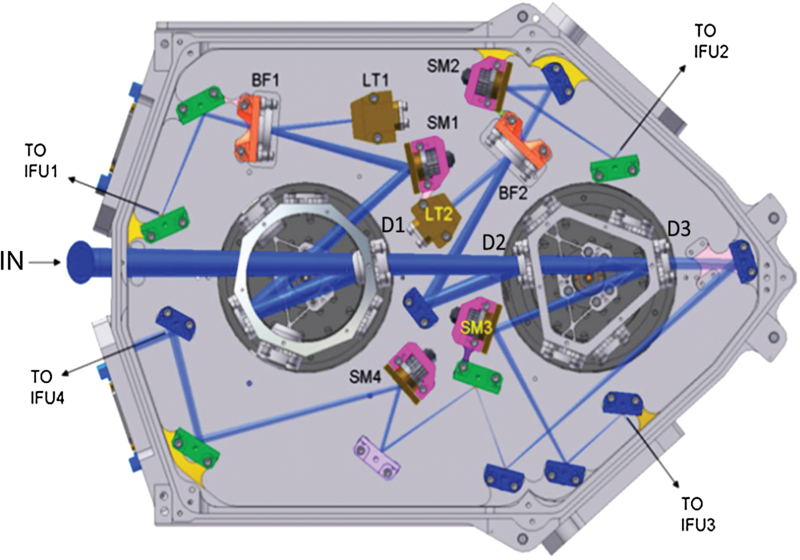
The low-resolution spectrograph (LRS) uses a double prism. The medium resolution spectrometer (MRS) uses dichroics for sub-band selection and gratings for spectral dispersion. The complex and compact design of the spectrometer allows the selection of 3 sets of sub-bands via dichroics and gratings mounted on the axes of 2 wheels. Image slicers are used to spatially reformat the field of view into a series of slits as necessary for the input to the relevant grating.
On this page
Low resolution spectrograph (LRS)
Double prism
See also: MIRI Low Resolution Spectroscopy, MIRI Optics and Focal Plane
The LRS slit is located at the telescope focal plane (along with the coronagraph masks).
Expected efficiency for the set of prisms is near 80% from 5 to 10 μm (at cold temperatures) but drops below 25% for wavelengths longer than 12 μm if slit losses are included. To mitigate the effect of the fold-over in the dispersion profile, a filter is mounted on the slit to block light at wavelengths short of 4.5 μm.
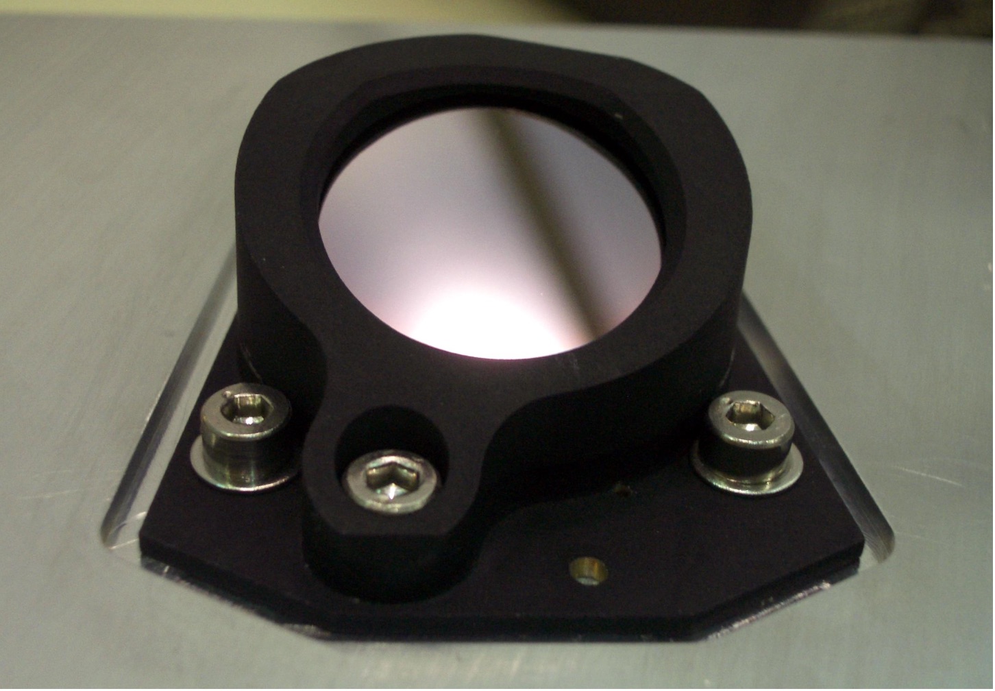
The flight model of the LRS double prism assembly (DPA), showing the ZnS side. © Fischer et al. 2008.
Medium resolution spectrograph (MRS)
Integral field units (IFUs)
See also: MIRI Medium Resolution Spectroscopy, JWST Integral Field Spectroscopy
The MIRI MRS has 4 separate integral field units (IFUs) called channels 1, 2, 3 and 4. Each IFU covers a separate wavelength range between 4.9 to 27.9 μm. An IFU serves primarily to divide a field of view into multiple slitlets suitable for grating dispersion. Its design has several advantages: (1) easier acquisition of point sources, (2) no slit losses due to vignetting, and (3) allowance for spatial variations as a function of wavelength for which a slit cannot account.
The MIRI IFU design consists of several components, including an entrance pupil, an input fold mirror, an image slicer mirror, a mask carrying exit pupils for the individual sliced images, a mask carrying slitlets for the individual images, and an array of reimaging mirrors behind the slitlets.
Three-dimensional view of the channel 3 IFU with labels identifying the major components, including an entrance pupil, an input fold mirror, an image slicer mirror, a mask carrying exit pupils for the individual sliced images, a mask carrying slitlets for the individual images, and an array of reimaging mirrors behind the slitlets. © Wells et al. 2015.
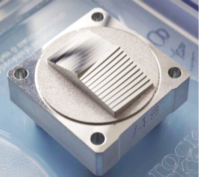
The slices are 1 mm wide and 12 mm long. © Wells et al. 2015/Cranfield University.
Dichroic filter/grating combination wheels
See also: MIRI Filters and Dispersers
Words in bold are GUI menus/
panels or data software packages;
bold italics are buttons in GUI
tools or package parameters.
© Max Planck Institute forAstronomy
References
European Space Agency (ESA), 2000- "JWST (James Webb Space Telescope)," Earth Observation Portal [Updated November 2017]
Wells, M. et al. 2015, PASP, 127, 646
The Mid-Infrared Instrument for the James Webb Space Telescope, VI: The Medium Resolution Spectrometer


