NIRCam Coronagraphic Occulting Masks and Lyot Stops

JWST NIRCam coronagraphy offers round and bar occulting masks paired with pupil plane Lyot stops, yielding inner working angles ranging from 0.13" to 0.89" HWHM (half-width at half-maximum).

On this page

Each NIRCam module includes a coronagraphic optical mount (COM) that carries 3 round and 2 bar-shaped coronagraphic occulting masks in the focal plane.

When centered on a bright point source, an occulting mask blocks the core of the point spread function (PSF). Diffracted light remaining in the PSF wings is blocked by a corresponding Lyot stop in the pupil plane. The pairing of the occulting mask and Lyot stop constitutes a "Lyot coronagraph," which enables high-contrast imaging of faint features near bright point sources.


Occulting masks

Words in bold are GUI menus/
panels or data software packages; 
bold italics are buttons in GUI
tools or package parameters.

Three round occulting masks are available in the pupil plane with sizes optimized for observations at different wavelengths. Table 1 gives their radii (in arcseconds) and the wavelengths at which those radii correspond to 6 resolution elements, or 6 λ/D, where D is the 6.5 m diameter of the JWST primary mirror. (Resolution at the diffraction limit is measured in units of λ/D.)

Table 1. 6λ/D wavelengths for the round occulting masks

Round coronagraphic mask

Radiusλ for 6λ/D
MASK210R0.40"2.1 μm
MASK335R0.63"3.35 μm
MASK430R0.81"4.3 μm


The 2 bar coronagraphic occulting masks are tapered, with radii varying by a factor of 3 along their lengths. Table 2 gives the half widths at half maximum (HWHM) at the bar end points and centers. Note these wavelengths extend beyond the observable range (see NIRCam Filters for Coronagraphy).


Table 2. 4λ/D wavelengths for the end points and center (in HWHM) of each bar coronagraphic mask

Bar coronagraphic maskHWHMλ for 4λ/D


MASKSWB

0.13"1.03 μm
0.26"2.1 μm
0.39"3.1 μm


MASKLWB

0.29"2.5 μm
0.59"4.6 μm
0.87"6.9 μm


Nominal inner working angles (IWAs) reported in Tables 1 & 2 correspond to the half-width at half-maximum (HWHM), the angular distance at which the coronagraph throughput is half. For the round masks it was designed to be at ~6λ/D and for the bar masks it was designed to be ~4λ/D for each given filter's central wavelength to which a special "fiducial" pointing is assigned as shown in Figure 1.

When a bar mask is used with a given filter, the source is placed behind the occulter at a position (shown in Figure 1) that provides HWHM = 4λ/D for the central wavelength λ of the filter.

Figure 1. NIRCam bar occulting masks and their corresponding nominal pointing positions for each filter

The NIRCam module A coronagraphic substrate is shown with marked nominal pointing positions for each filter. The large back rectangles correspond to the neutral density filters used for coronagraphic target acquisition on bright sources.
Figure 2. NIRCam coronagraphic occulting masks

NIRCam coronagraphic occulting masks and neutral-density squares for target acquisition

The NIRCam module A coronagraphic substrate, which includes bar and round masks for occulting bright objects and 5" × 5" neutral density squares for acquisition of bright targets (K < 7). The three lines of information at the top are the nominal wavelength range, mask name, and inner working angle for each occulting mask. The etched metal patterns deliver the desired radial profiles within tolerances. Adapted from Krist et al. 2010, Figure 3.
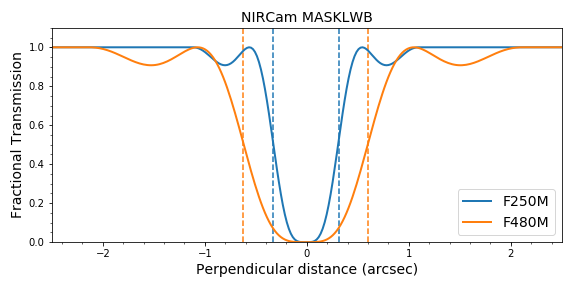
The filter transmission changes with radius and is different for each occulting mask (Figure 3).
 Figure 3. Filter transmission as a function of distance for round and bar masks

Transmission changes with distance and with the occulter. The plots for the bar masks show the allowed filter range. Vertical lines mark the 50% transmission point. The files used to create these plots are available here: transmissions.tar.


Lyot stops

In each module, NIRCam has 2 Lyot stops: one designed to suppress diffracted light from the round occulters, and the other to suppress diffracted light from the bar occulters. The final PSF is the Fourier transform of the Lyot stop. The geometrical transmission (Figure 4, c and d) of the Lyot stops is ~20%.

Figure 4. NIRCam coronagraph diffraction and Lyot stops

Diffraction from the NIRCam occulting masks (top row) and Lyot stops designed to suppress diffracted light (bottom row) from the round occulters (left) and bar occulters (right). In all images, white indicates light transmission. © Mao et al. 2011.

Additional throughput losses: other absorbing materials

The focal plane masks or occulters are physically made with aluminum dots on a 66 mm by 22 mm by 2 mm sapphire substrate whose transmission also slightly depends on wavelength.

Each of the 4 Lyot stops (one for the round occulter, one for the bar occulter, 2 modules) are mounted on a substrate whose wedge shifts the field of view by several tens of arcseconds (with respect to plain imaging) and images the occulters onto the detectors. The wedges' transmission is more chromatic for the SW as the substrate is BaF(~95% at 1 µm and around ~75% at 2.5 µm, around ~80% for most of the coronagraphic filters). For the LW wedges, the substrate material is Si and with > 95%–98% transmission between 3 µm and 5 µm.

Overall the NIRCam coronagraphic optics introduce a pure loss in throughput (> 1" away from the center of each occulter) of the order of a factor ~7 to ~10. In the JWST Exposure Time Calculator (ETC), a "total system throughput" plot is displayed for each given instrument setup.

Resulting focal plane images

Examples of in-flight focal plane images resulting from the two Lyot stop geometries are shown in Figure 5, unnocculted (TA, TA Confirmation 1) and occulted (TA Confirmation 2).

Figure 5. NIRCam coronagraph in-flight focal plane images resulting from the two Lyot stop geometries

In-flight focal plane images (top: round MASK335R, bottom: bar MASKLWB, both through the F335M filter) resulting from the two Lyot stop geometries are shown in Figure 5, unnocculted (TA, TA confirmation 1, left and middle) and occulted (TA confirmation 2, right most). These images were acquired during commissioning (Program 1441).


References

Girard, J. H., et al. 2022, Proceedings of the SPIE, 121803Q
JWST/NIRCam Coronagraphy: commissioning and first on-sky results

Krist, J., et al., 2010, SPIE, 77313J
The JWST/NIRCam coronagraph flight occulters

Mao, Y., et al., 2011, SPIE, 81500E
NIRCam coronagraphic Lyot stop: design, fabrication, and testing


Latest updates
  •  
    Added focal plane images (on-sky)

  •   
    Added figure: nominal pointing positions

  •  
    Added figures: transmission vs. radius
Originally published