NIRSpec IRS2 Detector Readout Mode
The JWST NIRSpec IRS2 readout mode improves NIRSpec detector noise performance by interspersing reference pixel reads with science pixels. Two readout patterns are available for the NIRSpec IRS2 readout mode.
On this page
Words in bold are GUI menus/
panels or data software packages;
bold italics are buttons in GUI
tools or package parameters.
Currently, NIRSpec target acquisition cannot be done with IRS2 readout patterns because of increased complexity in onboard processing for the IRS2 readout mode. Switching from a traditional readout pattern to an IRS2 readout pattern (or vice versa) may lead to thermal transients, and thus may affect the detector stability. As a consequence, the noise performance of an IRS2 science exposure following a target acquisition can be affected by up to 20 min.
What is IRS2?
Moseley et al. (2010) have characterized the noise properties of the NIRSpec detector system and determined that the noise is dominated by 1/frequency ("1/f") components that are highly correlated in time (across outputs and reference pixels) as shown in Figure 1.
In order to significantly reduce the correlation and achieve lower total noise, Moseley et al. (2010) have devised a modification of the traditional readout mode that (i) reads more reference pixels more frequently and (ii) digitizes the value of the reference output and sends it to the ground for post-processing and optimal subtraction.
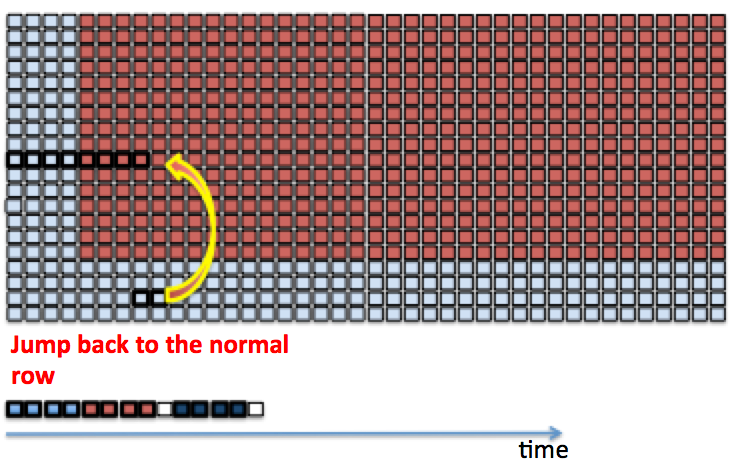
Contrary to the traditional readout mode, where the reference pixels are sampled in only a few rows and columns around the outside edges of the detector array, the IRS2 readout pattern regularly interleaves sampling of reference pixels with the sampling of normal pixels. The detector electronics samples 2 reference pixels twice for every 8 normal pixels (e.g., [8 normal, 2 × 2 reference, 8 normal], [8n, 2 × 2 ref, 8n] ... repeat.). Figure 2 shows an expanded example graphic of the key steps in the IRS2 readout process.
Because of the benefits of decreased correlated detector noise, use of the NIRSpec IRS2 readout mode for science observations is recommended in most cases. By suppressing 1/f noise, the IRS2 readout scheme leads to more uniform background measurements across the detector. Despite the fact that changing from a traditional mode like NRS to NRSIRS2 adds some overhead time and can lead to some thermal transients, using IRS2 mode is nevertheless recommended for all programs that benefit from reduced 1/f noise. Following target acquisition (which cannot use IRS2 mode as explained above), any thermal transients will mostly have settled by the time it takes to reconfigure the MSA and set up the exposures at the start of science observations. However, it is not recommended to switch between IRS2 and traditional patterns within a science observation block. Users should follow the guidelines in the NIRSpec Detector Recommended Strategies article to figure out which readout mode is best for their target.
In addition to the increased reference pixel sampling, the IRS2 readout mode also saves the value of a 5th output channel, the so-called reference output, which is sampled simultaneously to the clocking of any pixel in the array. In traditional readout mode, the signal in the reference output is subtracted analogically from the signal of each pixel readout. This happens before the analog signal is digitized by the SIDECAR ASIC and sent to the solid state recorder (SSR). In IRS2 readout, this 5th channel is saved along with the science data and increased reference pixel reads. Because this 5th channel is saved, the NIRSpec IRS2 readout patterns result in ~20% higher data volume than the traditional readout patterns.
Figure 3 presents the data structure of frames acquired in IRS2 readout mode, showing the science pixels, reference pixels, and reference output data. Due to the additional 4 reads every 16 regular pixels, in IRS2 mode, each output channel is mapped into a 640 × 2048 array instead of the 512 × 2048 array of the traditional mode. Individual frames of IRS2 data therefore have (3200 × 2048) pixels, and the size of IRS2 MULTIACCUM up-the-ramp integrations is (3200 × 2048) pixels × Ngroups. The enhanced noise correction enabled by the IRS2 readout mode is carried out in the calibration pipeline during the reference pixel subtraction step.
The IRS2 readout patterns NRSIRS2RAPID and NRSIRS2
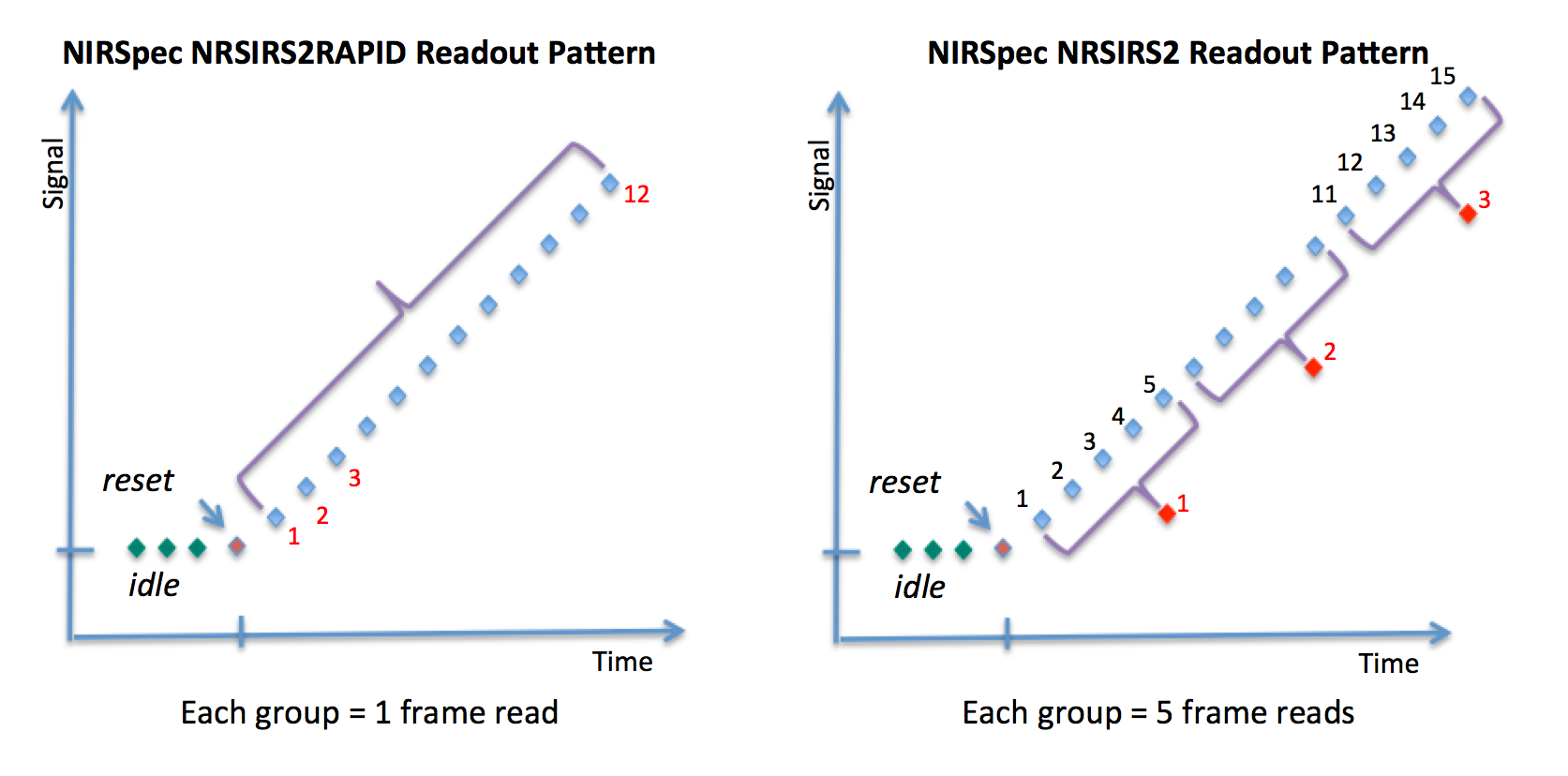
Table 1 and Figure 4 show the 2 readout patterns available in IRS2 readout mode. These patterns are NRSIRS2RAPID and NRSIRS2. Similar to traditional mode, NRSIRS2RAPID saves every frame that is read, so Nframes = 1 per group and the group time is 14.58 s. This time is longer than a single group time in the traditional readout pattern NRSRAPID, because of the increased time needed to intersperse the reference pixel reads. To preserve data recording volume, the NRSIRS2 pattern uses 5 frames per group compared to the 4 frames per group in the traditional readout pattern NRS. So, Nframes = 5 and the the group time is 72.944 s in NRSIRS2. In practice, using the NRSIRS2RAPID readout pattern with frequent recording of data groups is preferable and encouraged for all science use cases with no data volume limitations (the JWST Astronomer's Proposal Tool (APT) will warn users if data volume is an issue for an observing program).
Table 1. NIRSpec IRS2 readout patterns
| Detector readout type | NIRSpec readout pattern name | Nframes per group | Group time (s) | Measured total noise in ~950 s (e–) | |
|---|---|---|---|---|---|
| Detector NRS1 | Detector NRS2 | ||||
| IRS2 | NRSIRS2RAPID | 1 | 14.58889 | 5.9 † | 7.2 † |
| NRSIRS2 | 5 | 72.94445 | |||
† Detector noise measured during commissioning in NRSIRS2RAPID dark exposures, includes effects of cosmic rays after mitigation.
Data processing for IRS2 readouts to decrease noise
The IRS2 readout can improve 1/f correlated detector noise performance compared to the traditional readout by allowing more accurate pipeline subtraction of any electronic drifts which are tracked by the increased sampling of reference pixels (see Figure 5). The adopted methodology for processing IRS2 data is described in detail in Rauscher et al. (2012). The primary difference in processing comes in the reference pixel subtraction step of the pipeline data reduction. All reference pixel analysis and subtraction for IRS2 readout is done in Fourier space. The pixels are arranged in a time series for each of the 5 data outputs. The reference output and the reference pixels that track the detector electronic characteristics are filtered in the frequency domain before being subtracted from each of the regular pixels.
Analysis shows that the noise is stationary, and components are independent in the Fourier domain. As a result, a set of dark exposures is used to derive the reference information characteristics for each of the output (for each SCA). This results in a set of IRS2 reference files that are used in Fourier space to anchor the measured reference pixels and output to correct the science data. The IRS2 reference pixel subtraction method reduces the (3200 × 2048) pixel raw data frames into (2048 × 2048) pixel processed frames, thus matching the size of traditional mode data. All subsequent data pipeline steps process the IRS2 and traditional readout data in the same manner.
More information on the IRS2 reference pixel processing can be found in Rauscher et al. (2012).
References
Rausher, B. J., et al. 2012 SPIE 8543
Reducing the read noise of HAWAII-2RG detector systems with improved reference sampling and subtraction (IRS2)
Rauscher, B. J. et al. 2017, PASP, 129, 105003
Improved Reference Sampling and Subtraction: A Technique for Reducing the Read Noise of Near-infrared Detector Systems”,
Moseley, S. H., et al. 2010 SPIE 7742
Reducing the read noise of H2RG detector arrays: eliminating correlated noise with efficient use of reference signals


