NIRISS Detector Readout
The JWST NIRISS detector is read out non-destructively using 4 outputs for the full array and one output for the subarrays.
NIRISS detectors use MULTIACCUM readout mode
See also: Understanding Exposure Times, NIRISS Detector Readout Patterns, NIRISS Detector Subarrays
The NIRISS detector is read out in MULTIACCUM mode, where charge is continuously measured "non-destructively" rather than transferred across pixels as in CCDs. The detector is reset at the beginning of every NIRISS integration. The full specification of a readout involves defining the readout pattern and readout format.
Words in bold are GUI menus/
panels or data software packages;
bold italics are buttons in GUI
tools or package parameters.
NISRAPID will primarily be used for bright objects or observations requiring a high cadence, where data volume limits are not a concern, and mostly when using a subarray for readout. NIS is preferred for longer integrations of faint sources. An integration is specified by the number of groups between detector resets. There can be multiple integrations in an exposure.
The readout format denotes the spatial region of the detector to be read and is specified by the detector subarray. Fewer pixels are read out when using a NIRISS subarray compared with full frame readout, which results in a shorter frame time. The full frame readout mode is the only option available for WFSS and imaging science observations. The SOSS and AMI modes mostly use the subarray readout formats.
A schematic of the NIRISS detector array is illustrated in Figure 1. In full frame mode, 4 parallel output channels, 2048 × 512 pixels, are read out simultaneously. Subarrays are read through a single output channel.
Figure 1. The functional layout of the NIRISS detector array
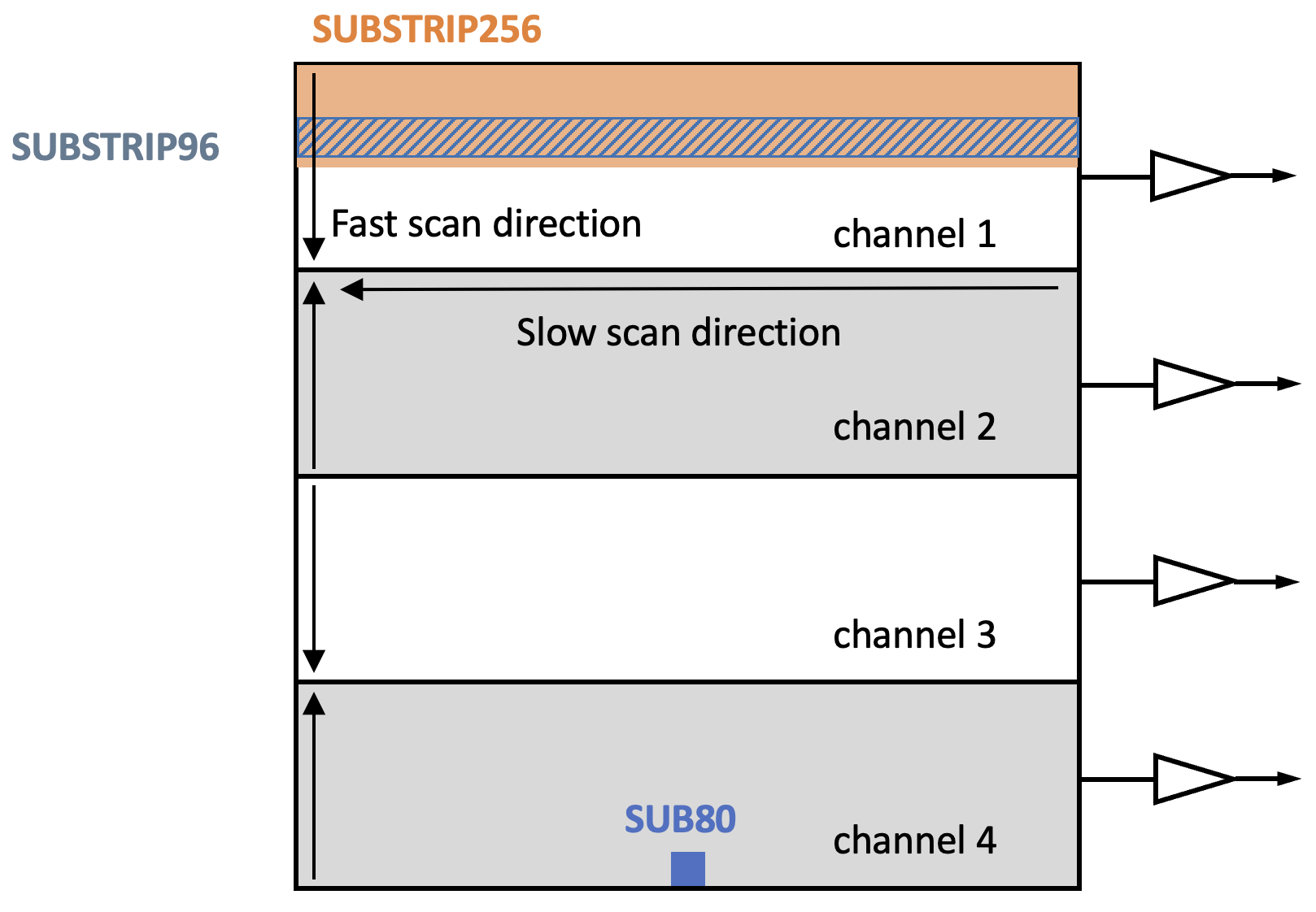
The 4-output mode shown here is used for the full array, while subarrays are readout in one-output mode. Shown are the 80 × 80 subarray for the AMI mode (SUB80) and the 2048 × 256 subarray (SUBSTRIP256) and 2048 × 96 subarray (SUBSTRIP96) for the SOSS mode.
NIRISS SOSS multistripe subarray readout
Beginning in Cycle 5, the NIRISS SOSS mode will also offer four "multistripe" subarrays that make use of a non-standard readout method. Instead of reading a single subarray region, the multistripe subarrays split the subarray into multiple regions (or "stripes") that are read out individually, with the stripe moving to a different location in the subarray after the integration for the previous stripe is completed. This method allows for the frame time to be dramatically reduced, and bright limit improved, at the expense of reduced exposure efficiency due to only a portion of the subarray being read out at a given time.
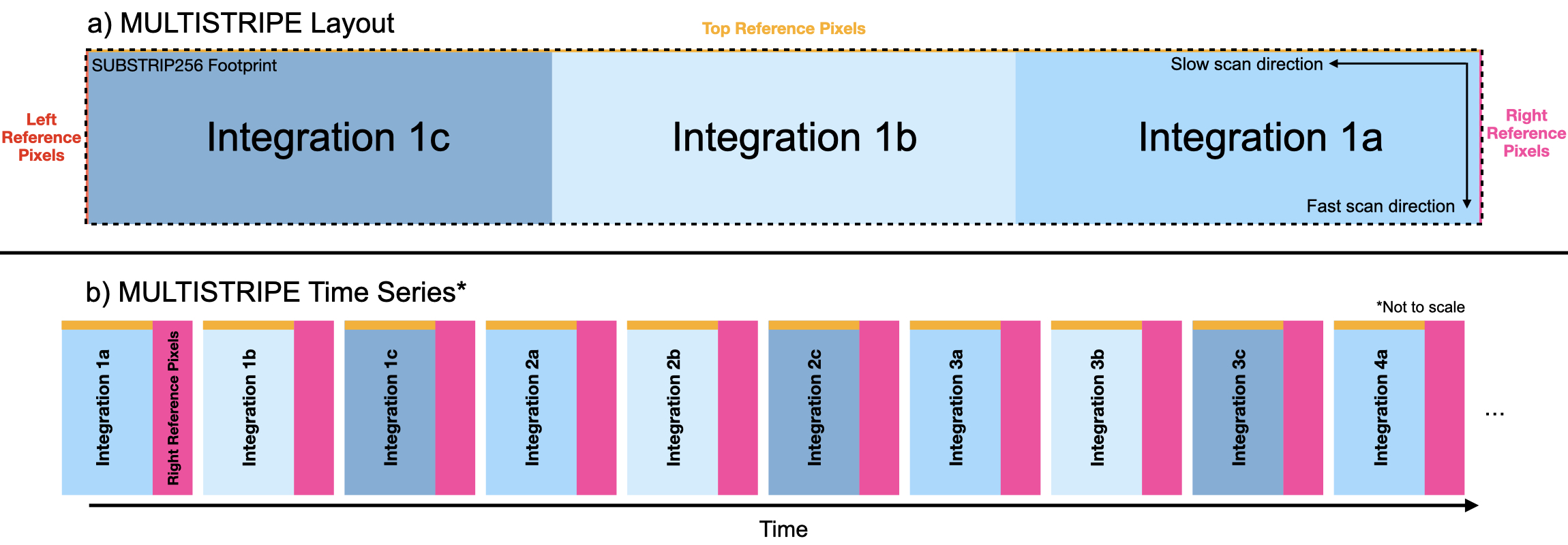
Figure 2a shows an example layout for the SUB680STRIPE_SOSS multistripe subarray, where the subarray is split between 3 individual stripes of width 680 pixels, a similar structure can be imagined for the smaller stripe sizes. Importantly, the 4 right-hand reference pixel columns are interleaved with each stripe to ensure that there are enough reference pixels perpendicular to the detector rows for calibration purposes. The top 4 rows of reference pixels fall within the stripes themselves, and the left-hand reference pixels are never read out.
Science observing with the new SOSS multistripe subarrays will begin after successful commissioning, nominally at the start of Cycle 5. ETC signal-to-noise predictions will be refined, once on orbit data are available.
Figure 2. The NIRISS SOSS multistripe footprint and time series
Click on the figure for a larger view.
The footprint (a) and time series (b) for the multistripe readout of the SUB680STRIPE_SOSS subarray. a) indicates how the subarray is split between the individual stripes, and their relative positions compared to the reference pixels and the scan directions. b) is no longer to scale, but shows the order in which the different areas of the subarray are read out throughout the read out sequence. Here, you can see that the right-hand reference pixels are read out with each stripe, the top reference pixels are read out within the stripes themselves, and the left hand reference pixels are never read out.