NIRSpec MSA Leakage Correction for IFU Observations
MSA flux leakage correction for the IFU mode observations is the correction carried out for excess flux that can affect science exposures in the IFU mode, due to light that makes its way through the MSA shutters.
See also: NIRSpec MSA Leakage Subtraction Recommended Strategies, NIRSpec Bright Spoilers and the IFU Recommended Strategies
The MSA has a population of shutters that are permanently or intermittently stuck in an open configuration. These "failed open" MSA micro-shutters can be a problem when using the NIRSpec IFU observing mode. Even though the MSA is configured "all closed" for NIRSpec IFU exposures, the failed open shutters are always open, and always recording flux from the sky. In sparse fields, the failed open shutters may record only excess background flux. However, in very crowded fields, IFU spectra will likely be contaminated by the spectra of field objects seen through these failed open MSA shutters.
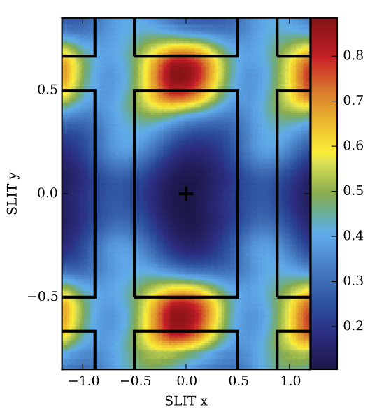
Observations with the IFU can also be affected by the MSA flux leakage problem (Figure 1) where light from the sky can pass through closed MSA shutters at specific locations. This is also referred to as "MSA print-through." Figure 1 is a zoomed view, made from combining imaging mode ground test data from many shutters. It shows a super-sampled map of the leakage flux from the MSA; the color key highlights where the shutters are opaque (blue) and where a moderate amount of flux can leak through to the spectrograph (red). The colors presented are relative flux levels, and the red area shows that the leakage level (measured closed flux / measured open flux) is maximized at the tops and bottoms of shutters. The MSA leakage also varies spatially across the MSA, ranging from contrast levels of 2,000–3,000 to more than 10,000. It is important to keep in mind that the flux leakage is a cumulative effect from all the MSA shutters in the dispersion direction, and as a result, it can be detrimental to accurate background flux subtraction in IFU mode observations.
MSA leakage in IFU data and methods for correction
The flux leakage correction from failed open shutters and MSA print-through might be a problem for some IFU science cases. To obtain the highest data quality from the removal of excess flux leakage, the safest solution (and most expensive in terms of overheads) consists of closing the IFU aperture and obtaining an equivalent MSA leakage exposure for every science exposure acquired and at every dither position. These observations will then be used in post-processing to pairwise subtract the spectral contamination from failed open MSA shutters.
The subtraction of MSA leakage correction exposures for each dither provides the best correction. Another option is to take a single leakage exposure without dithering. Alternatively, either of these two types of leakage exposures can be obtained with a shorter exposure time than the science exposure, but note that this would cause the noise of the leakage-corrected observation to increase. The MSA leakage correction exposures will be subtracted as count rate images; the shorter exposure time would have the same count rates, determined with poorer accuracy.
The Astronomers Proposal Tool (APT) provides multiple options for creating leakage exposures, as outlined in Table 1.
Another solution to help mitigate the problem of failed open MSA shutters is to dither the observations. Dithering is a highly recommended observing strategy for all JWST observations. This is especially useful for filtering out leakage contamination from sources in failed open shutters during the combination of IFU data cubes from different dithers. Leakage exposures may be obtained at either all of the dither positions or only the first, as outlined in Table 1.
Table 1. Methods for creating leakage exposures for IFU datasets
| MSA leakage correction exposure options | Example science use cases |
|---|---|
Same exposure time as science; | The most accurate leakage subtraction in any field, however, it requires the most observing time to be spent away from science targets. |
Same exposure time as science; | Accurate background flux subtraction, e.g., when the MSA is in a sparse field with a spatially constant background flux. |
Shorter exposure time than science; | Decreased accuracy leakage subtraction; shorter exposures may be suitable for determining count rates to subtract bright objects in open MSA shutters, e.g., as in crowded fields. |
Shorter exposure time than science; | Decreased accuracy leakage subtraction; likely suitable for background subtraction in high flux environments (high zodiacal light). |
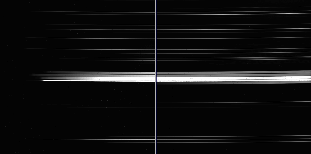
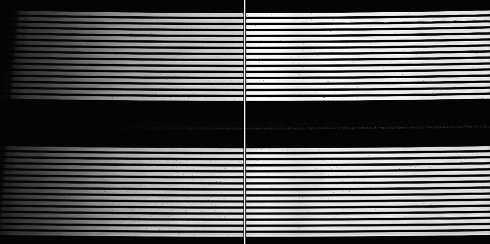
The simple process to carry out the MSA leakage correction in IFU data from failed open MSA shutters using pairwise exposure subtraction is shown in Figures 2, 3 and 4.
Figure 2 shows an IFU flat field exposure (with detector NRS1 on the left, NRS2 on the right). The 30 IFU slice spectra are apparent on the top and bottom portions of the detectors, and the fixed slit (FS) spectra are seen in the middle. Failed open MSA shutters are highlighted with blue arrows; their contaminating spectra are noticeable in the figure.
Figure 3 shows a corresponding IFU leakage correction flat field exposure acquired with the same exposure time using the MSA magnet arm blocking lid to cover the IFU entrance window. Again, the FS spectra and failed open MSA shutters are seen, but no IFU flux is apparent.
Figure 4 shows the result of subtracting the leakage exposure from the IFU flat field, which is the 30 IFU slice spectra have been cleaned of contamination.


