JWST Telescope
The Optical Telescope Element (OTE) of JWST consists of the primary, secondary, tertiary, and fine steering mirrors. The wavefront of the OTE is monitored and actively controlled.
On this page
See also: Wavefront Sensing and Control
The mirror system that collects and focuses light for JWST is referred to as the optical telescope element (OTE). It has a 3-mirror anastigmat design, consisting of primary, secondary, and tertiary mirrors. A 4th flat mirror, called the fine steering mirror (FSM), is used for pointing stabilization and very small offset maneuvers. The effective focal ratio of the OTE is f/20, and the effective focal length is 131.4 m.
The mirrors are made of beryllium, which is both lightweight and very stable to temperature variations over the range of 30–80 K. The mirrors are coated with gold to provide high reflectivity from 0.6 to just beyond 28 μm.
Optical design and components
Details on the optical design, manufacturing, and testing of the JWST OTE can be found in Lightsey et al. (2012) and Lightsey et al. (2014).
Details on the in-flight imaging performance of the JWST OTE can be found in Knight & Lightsey (2022)
Primary mirror
The primary mirror is comprised of 18 hexagonal segments, each ~1.4 m in diameter, which, when properly phased together, act as a single mirror ~6.5 m in diameter. The individual segments have, on average, better than 25 nm rms surface figure error. The primary mirror serves as the aperture stop for most JWST observing modes, with the exceptions of coronagraphy and aperture masking interferometry (AMI). The unobscured collecting area of the primary mirror is 25.4 m2. (The total polished area is slightly greater, 26.3 m2, but the secondary mirror support struts obscure a small portion.) An opaque border around the outer edge of the primary helps minimize stray light.
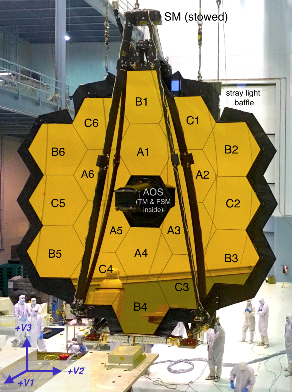
Each primary mirror segment has actuators on the back that allow control of the 6 spatial degrees of freedom with a precision better than 10 nm. A 7th actuator on each segment controls its radius of curvature, allowing correction for slight manufacturing variations to ensure all 18 segments' focal lengths are very closely matched. Two segments needed larger radius of curvature corrections than the rest, and as a result, have somewhat higher surface residuals. These segments were positioned in the primary in locations blocked by the Lyot stops and aperture mask, specifically positions A1 and C3, thus minimizing the wavefront error for the coronagraphy and aperture masking modes which are most sensitive to such residuals.
Secondary mirror
The secondary mirror is a convex circular mirror 0.74 m in diameter. A set of 6 actuators allows control of the mirror's position and orientation, similar to the control of the primary segments. The primary and secondary first bring light to an initial Cassegrain focus just before the entrance aperture of the aft optics system, where a fixed baffle also helps to block stray light.
Aft optics
The aft optics system contains a fixed tertiary mirror and movable FSM. The tertiary mirror is a concave aspheric mirror with an elongated shape roughly 0.73 × 0.52 m in size. It re-images the primary aperture onto the FSM, while canceling out aberrations to provide excellent image quality over the full field of view. Like the primary and secondary mirrors, the tertiary mirror surface figure is better than 25 nm rms. Because the tertiary is at an intermediate focal plane, in-between a focal plane and pupil plane, images taken at different field positions will see different pieces of that surface figure. This will be one of the factors contributing to field dependence of point spread functions. See Lightsey et al. (2014) for more details.
The FSM is a high quality flat mirror used to stabilize the image during science observations. During observations, it will be continuously adjusted in X- and Y-axis tilts based on measurements made by the attitude control system as part of the fine guidance control loop. The OTE exit pupil is the image of the primary that reflects off the fine steering mirror towards the ISIM focal plane and instruments. A mask around the outer edge of the fine steering mirror helps further minimize stray light.

Deployments and wavefront control
The telescope was phased during on-orbit commissioning; and the wavefront is being routinely monitored during science operations and corrected as needed to maintain alignments.
The primary mirror segments are mounted on a graphite-composite backplane structure that is designed to be very stable. Two "wings", each supporting three mirror segments (B2, C2, B3 and B5, C5, B6 in Figure 1 above), were folded at launch, and deployed once on orbit, latching firmly into their permanent positions. The secondary is supported by a deployable tripod support structure which also latched into position following deployment. These large deployments happened within the first few weeks after launch while the observatory was en route to L2.
Bringing the mirrors from their initial deployed positions into fine alignment required a long series of small iterative adjustments that made use of several different variations of wavefront sensing and control.
Several OTE electronics boxes support the use of actuator mechanisms and related sensors for position, and to handle telemetry. An actuator drive unit in the spacecraft interfaces with these electronic boxes. Notably, the actuator drive unit can either run the FSM control loop, or send adjustments to the primary and secondary actuators, but not both tasks at once. Thus, during science observations when the fine steering loop is active, the other mirrors will always be static and fixed in position. The OTE electronics system is fully redundant for robust fault tolerance in flight.
Performance
The OTE was required to be diffraction limited for wavelengths λ > 2 μm, with predictions for the full observatory wavefront error level (telescope plus instrument plus dynamics) being better than 100 nm rms WFE at NIRCam. See Lightsey et al. (2014) for details of pre-flight modeling, requirements, and predictions.
In fact, the optical performance measured at the end of commissioning and into science operations exceeds expectations, with, for example, the OTE plus NIRCam SW showing diffraction-limited image quality at ∼1.1 μm, and observatory level WFE at NIRCam usually between 60 and 80 nm rms. A complete discussion of the telescope’s optical performance against requirements at the end of commissioning is reported in Knight & Lightsey (2022) and Rigby et al. (2022).
References
Gardner, J. P. et al. 2006, Space Sci.Rev., 123, 485
The James Webb Space Telescope
Knight, J.S. & Lightsey, P.A. 2022, SPIE 12180, 121800V
Lightsey, P. A. et al. 2012, Optical Engineering, 51, 011003
James Webb Space Telescope: Large deployable cryogenic telescope in speace
Lightsey, P. A. et al. 2014, SPIE 9143, 914304-1
Status of the Optical Performance for the James Webb Space Telescope
Rigby, J. et al. 2022, arXiv:2207.05632
Characterization of JWST science performance from commissioning
WebbPSF tool (converts predicted OTE performance and related data into simulated JWST point spread functions as seen by each of the instruments)